Chapter 26: 7, 16, 21, 33, 45, 50, 68
advertisement

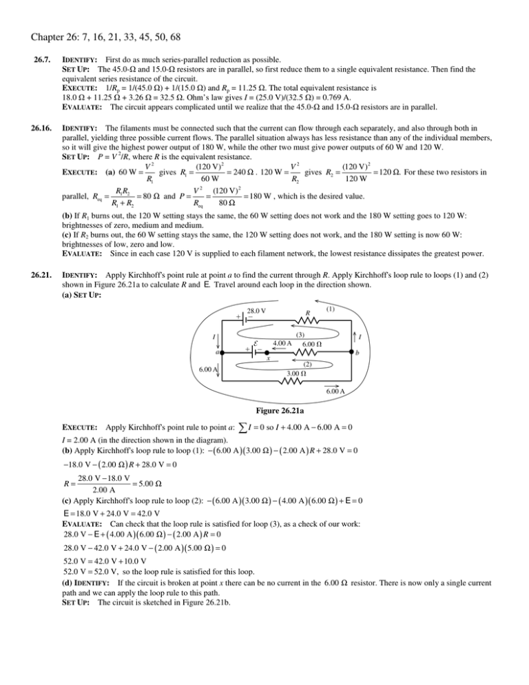
Chapter 26: 7, 16, 21, 33, 45, 50, 68 26.7. 26.16. IDENTIFY: First do as much series-parallel reduction as possible. SET UP: The 45.0- and 15.0- resistors are in parallel, so first reduce them to a single equivalent resistance. Then find the equivalent series resistance of the circuit. EXECUTE: 1/Rp = 1/(45.0 ) + 1/(15.0 ) and Rp = 11.25 . The total equivalent resistance is 18.0 + 11.25 + 3.26 = 32.5 . Ohm’s law gives I = (25.0 V)/(32.5 ) = 0.769 A. EVALUATE: The circuit appears complicated until we realize that the 45.0- and 15.0- resistors are in parallel. IDENTIFY: The filaments must be connected such that the current can flow through each separately, and also through both in parallel, yielding three possible current flows. The parallel situation always has less resistance than any of the individual members, so it will give the highest power output of 180 W, while the other two must give power outputs of 60 W and 120 W. SET UP: P = V 2/R, where R is the equivalent resistance. V2 (120 V) 2 V2 (120 V) 2 = 240 Ω . 120 W = = 120 Ω. For these two resistors in EXECUTE: (a) 60 W = gives R1 = gives R2 = R1 60 W R2 120 W RR V 2 (120 V) 2 parallel, Req = 1 2 = 80 Ω and P = = = 180 W , which is the desired value. R1 + R2 Req 80 Ω (b) If R1 burns out, the 120 W setting stays the same, the 60 W setting does not work and the 180 W setting goes to 120 W: brightnesses of zero, medium and medium. (c) If R2 burns out, the 60 W setting stays the same, the 120 W setting does not work, and the 180 W setting is now 60 W: brightnesses of low, zero and low. EVALUATE: Since in each case 120 V is supplied to each filament network, the lowest resistance dissipates the greatest power. 26.21. IDENTIFY: Apply Kirchhoff' s point rule at point a to find the current through R. Apply Kirchhoff' s loop rule to loops (1) and (2) shown in Figure 26.21a to calculate R and E. Travel around each loop in the direction shown. (a) SET UP: Figure 26.21a EXECUTE: Apply Kirchhoff' s point rule to point a: I = 0 so I + 4.00 A − 6.00 A = 0 I = 2.00 A (in the direction shown in the diagram). (b) Apply Kirchhoff' s loop rule to loop (1): − ( 6.00 A )( 3.00 Ω ) − ( 2.00 A ) R + 28.0 V = 0 −18.0 V − ( 2.00 Ω ) R + 28.0 V = 0 28.0 V − 18.0 V = 5.00 Ω 2.00 A (c) Apply Kirchhoff' s loop rule to loop (2): − ( 6.00 A )( 3.00 Ω ) − ( 4.00 A )( 6.00 Ω ) + E = 0 R= E = 18.0 V + 24.0 V = 42.0 V EVALUATE: Can check that the loop rule is satisfied for loop (3), as a check of our work: 28.0 V − E + ( 4.00 A )( 6.00 Ω ) − ( 2.00 A ) R = 0 28.0 V − 42.0 V + 24.0 V − ( 2.00 A )( 5.00 Ω ) = 0 52.0 V = 42.0 V + 10.0 V 52.0 V = 52.0 V, so the loop rule is satisfied for this loop. (d) IDENTIFY: If the circuit is broken at point x there can be no current in the 6.00 Ω resistor. There is now only a single current path and we can apply the loop rule to this path. SET UP: The circuit is sketched in Figure 26.21b. Figure 26.21b EXECUTE: +28.0 V − ( 3.00 Ω ) I − ( 5.00 Ω ) I = 0 28.0 V = 3.50 A 8.00 Ω EVALUATE: Breaking the circuit at x removes the 42.0 V emf from the circuit and the current through the 3.00 Ω resistor is reduced. I= 26.33. IDENTIFY: The meter introduces resistance into the circuit, which affects the current through the 5.00-k resistor and hence the potential drop across it. SET UP: Use Ohm’s law to find the current through the 5.00-k resistor and then the potential drop across it. EXECUTE: (a) The parallel resistance with the voltmeter is 3.33 k , so the total equivalent resistance across the battery is 9.33 k , giving I = (50.0 V)/(9.33 k ) = 5.36 mA. Ohm’s law gives the potential drop across the 5.00-k resistor: V5 k = (3.33 k )(5.36 mA) = 17.9 V (b) The current in the circuit is now I = (50.0 V)/(11.0 k ) = 4.55 mA. V5 k = (5.00 k )(4.55 mA) = 22.7 V. (c) % error = (22.7 V – 17.9 V)/(22.7 V) = 0.214 = 21.4%. (We carried extra decimal places for accuracy since we had to subtract our answers.) EVALUATE: The presence of the meter made a very large percent error in the reading of the “true” potential across the resistor. 26.45. IDENTIFY: The stored energy is proportional to the square of the charge on the capacitor, so it will obey an exponential equation, but not the same equation as the charge. SET UP: The energy stored in the capacitor is U = Q2/2C and the charge on the plates is Q0 e–t/RC. The current is I = I0 e–t/RC. EXECUTE: U = Q2/2C = (Q0 e–t/RC)2/2C = U0 e–2t/RC When the capacitor has lost 80% of its stored energy, the energy is 20% of the initial energy, which is U0/5. U0/5 = U0 e–2t/RC gives t = (RC/2) ln 5 = (25.0 )(4.62 pF)(ln 5)/2 = 92.9 ps. At this time, the current is I = I0 e–t/RC = (Q0/RC) e–t/RC, so I = (3.5 nC)/[(25.0 )(4.62 pF)] e–(92.9 ps)/[(25.0 )(4.62 pF)] = 13.6 A. EVALUATE: When the energy reduced by 80%, neither the current nor the charge are reduced by that percent. 26.50. IDENTIFY: P = VI = I 2 R SET UP: Problem 25.77 says that for 12-gauge wire the maximum safe current is 2.5 A. P 4100 W EXECUTE: (a) I = = = 17.1 A. So we need at least 14-gauge wire (good up to 18 A). 12 gauge is also ok (good up to V 240 V 25 A). V2 V 2 (240 V) 2 (b) P = and R = = = 14 Ω . R P 4100 W (c) At 11c/ per kWH, for 1 hour the cost is (11c/kWh)(1 h)(4.1 kW) = 45c/ . / EVALUATE: The cost to operate the device is proportional to its power consumption. 26.68. IDENTIFY: The current through the 40.0 Ω resistor equals the current through the emf, and the current through each of the other resistors is less than or equal to this current. So, set P40 = 1.00 W and use this to solve for the current I through the emf. If P40 = 1.00 W , then P for each of the other resistors is less than 1.00 W. SET UP: Use the equivalent resistance for series and parallel combinations to simplify the circuit. EXECUTE: I 2 R = P gives I 2 (40 Ω) = 1 W , and I = 0.158 A . Now use series / parallel reduction to simplify the circuit. The upper parallel branch is 6.38 Ω and the lower one is 25 Ω . The series sum is now 126 Ω . Ohm’s law gives E = (126 Ω)(0.158 A) = 19.9 V . EVALUATE: The power input from the emf is EI = 3.14 W , so nearly one-third of the total power is dissipated in the 40.0 Ω resistor.


