UCSD Summer Session Physics 2B Formula Sheet
advertisement
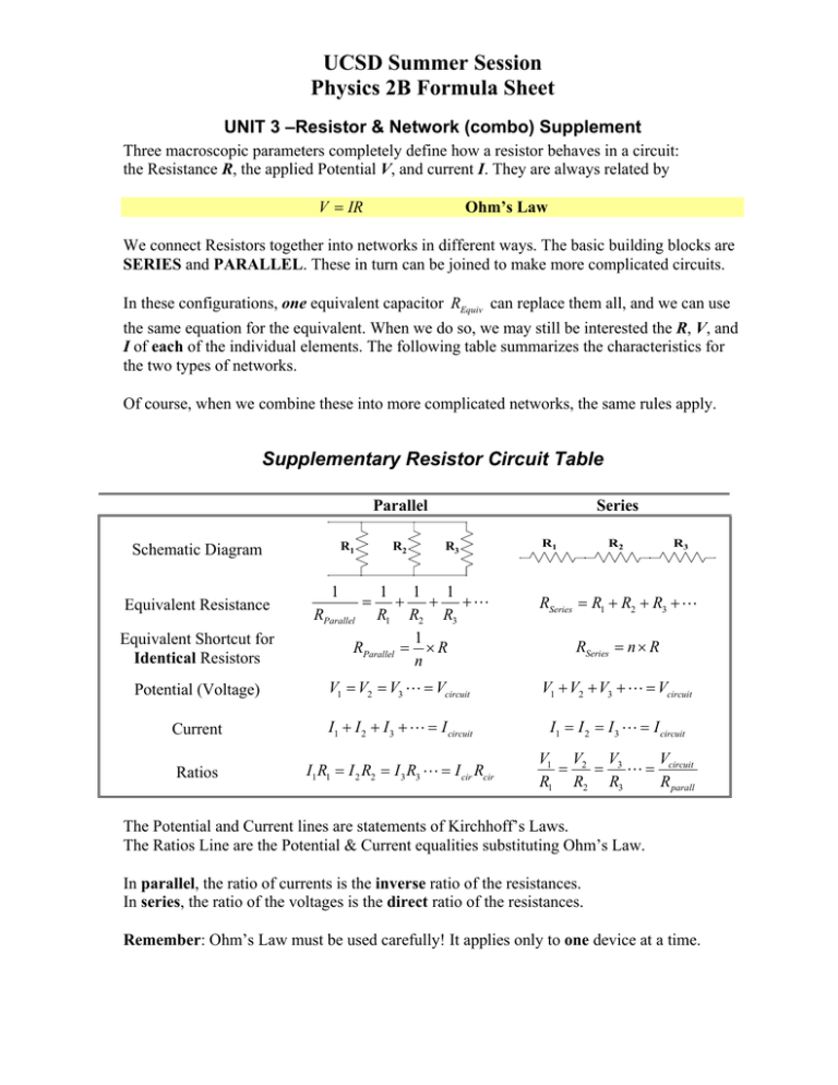
UCSD Summer Session Physics 2B Formula Sheet UNIT 3 –Resistor & Network (combo) Supplement Three macroscopic parameters completely define how a resistor behaves in a circuit: the Resistance R, the applied Potential V, and current I. They are always related by V = IR Ohm’s Law We connect Resistors together into networks in different ways. The basic building blocks are SERIES and PARALLEL. These in turn can be joined to make more complicated circuits. In these configurations, one equivalent capacitor REquiv can replace them all, and we can use the same equation for the equivalent. When we do so, we may still be interested the R, V, and I of each of the individual elements. The following table summarizes the characteristics for the two types of networks. Of course, when we combine these into more complicated networks, the same rules apply. Supplementary Resistor Circuit Table Parallel R1 Schematic Diagram R3 R1 R2 R3 RSeries = R1 + R2 + R3 +" Equivalent Shortcut for Identical Resistors 1 1 1 + + +" RParallel R1 R2 R3 1 RParallel = × R n Potential (Voltage) V1 = V2 = V3 " = Vcircuit V1 + V2 + V3 + " = Vcircuit Current I1 + I 2 + I 3 + " = I circuit I1 = I 2 = I 3 " = I circuit Ratios I1 R1 = I 2 R2 = I 3 R3 " = I cir Rcir V V1 V2 V3 = = " = circuit R1 R2 R3 R parall Equivalent Resistance 1 R2 Series = RSeries = n × R The Potential and Current lines are statements of Kirchhoff’s Laws. The Ratios Line are the Potential & Current equalities substituting Ohm’s Law. In parallel, the ratio of currents is the inverse ratio of the resistances. In series, the ratio of the voltages is the direct ratio of the resistances. Remember: Ohm’s Law must be used carefully! It applies only to one device at a time.

