Pulsed Power Supply
advertisement

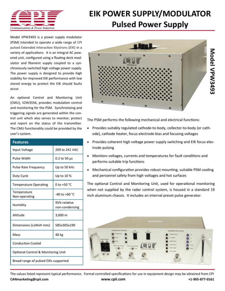
EIK POWER SUPPLY/MODULATOR Pulsed Power Supply An optional Control and Monitoring Unit (CMU), VZW3556, provides modulation control and monitoring for the PSM. Synchronizing and triggering signals are generated within the control unit which also serves to monitor, protect and report on the status of the transmitter. The CMU functionality could be provided by the user’s system. Model VPW3493 Model VPW3493 is a power supply modulator (PSM) intended to operate a wide range of CPI pulsed Extended Interaction Klystrons (EIK) in a variety of applications. It is an integral AC powered unit, configured using a floating deck modulator and filament supply coupled to a synchronously switched high voltage power supply. The power supply is designed to provide high stability for improved EIK performance with low stored energy to protect the EIK should faults occur. The PSM performs the following mechanical and electrical functions: Provides suitably regulated cathode-to-body, collector-to-body (or cath- ode), cathode heater, focus electrode bias and focusing voltages Provides coherent high voltage power supply switching and EIK focus elec- Features Input Voltage 209 to 241 VAC Pulse Width 0.2 to 50 µs Pulse Rate Frequency Up to 50 kHz Duty Cycle Up to 10 % Temperature Operating 0 to +50 °C Temperature Non-operating -40 to +60 °C Humidity 95% relative non-condensing Altitude 3,000 m Dimensions (LxWxH mm) 585x305x190 Mass 40 kg trode pulsing Monitors voltages, currents and temperatures for fault conditions and performs suitable trip functions Mechanical configuration provides robust mounting, suitable PSM cooling and personnel safety from high voltages and hot surfaces The optional Control and Monitoring Unit, used for operational monitoring when not supplied by the radar control system, is housed in a standard 19 inch aluminum chassis. It includes an internal preset pulse generator. Conduction Cooled Optional Control & Monitoring Unit Broad range of pulsed EIKs supported The values listed represent typical performance. Formal controlled specifications for use in equipment design may be obtained from CPI CANmarketing@cpii.com www.cpii.com +1-905-877-0161 Protection circuits are employed to prevent damage to the EIK and the PSM by inhibiting operation under the following conditions: Cathode warm-up high voltage delay Average Body over current Cathode over current Cathode voltage out of regulation Transmitter over-temperature EIK collector over-temperature or low coolant flow Modulator input not valid (pulse width and/or duty cycle out of range) These faults prevent or remove the application of high voltage to the EIK except “Modulator Input Not Valid” which will prevent pulsing but will not prevent the application of high voltage to the EIK. All high voltage assemblies (including the floating deck modulator) employ dielectric insulation to allow operation under the specified environmental conditions in any physical orientation. Typical Supply Control and monitoring unit (CMU) HV power supply/modulator (PSM) 3 m cable set for connecting CMU to PSM EIK with 0.4 m HV cables connecting EIK to PSM Typical Operating Values 201501VPW3493 ©CPI 2015 Cathode Voltage -12.5 to -21.0 kV wrt ground Heater Voltage -5.5 to -6.5 V wrt cathode Collector Voltage Collector depression Factory set Grid Voltage (off) -3.0 to -3.5 kV wrt cathode Grid Voltage (on) -55 to -10 V wrt cathode Cathode Current 750 mA Body Current 40 mA CPI Canada 45 River Dr, Georgetown, ON, L7G 2J4, Canada


