http://en.wikipedia.org/wiki/Involute_gear Conjugate action, involute
advertisement

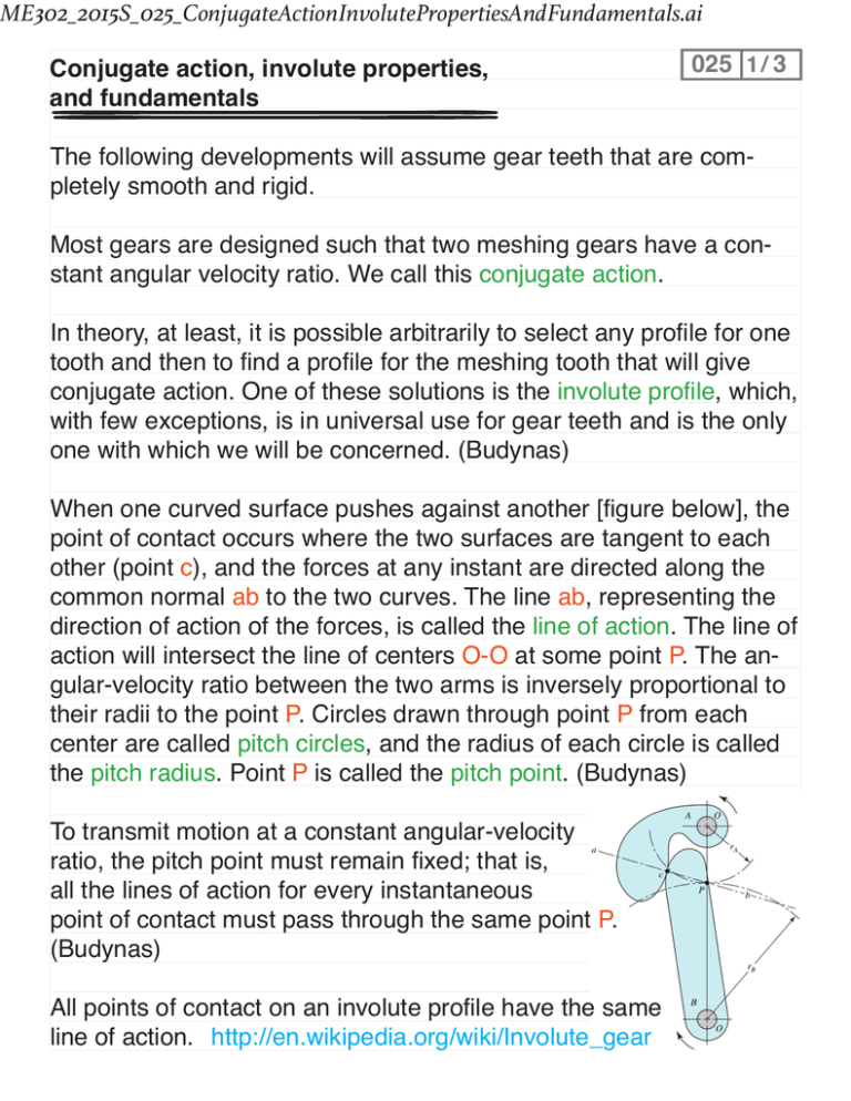
ME302_2015S_025_ConjugateActionInvolutePropertiesAndFundamentals.ai Conjugate action, involute properties, and fundamentals 025 1 / 3 The following developments will assume gear teeth that are completely smooth and rigid. Most gears are designed such that two meshing gears have a constant angular velocity ratio. We call this conjugate action. In theory, at least, it is possible arbitrarily to select any profile for one tooth and then to find a profile for the meshing tooth that will give conjugate action. One of these solutions is the involute profile, which, with few exceptions, is in universal use for gear teeth and is the only one with which we will be concerned. (Budynas) When one curved surface pushes against another [figure below], the point of contact occurs where the two surfaces are tangent to each other (point c), and the forces at any instant are directed along the common normal ab to the two curves. The line ab, representing the direction of action of the forces, is called the line of action. The line of action will intersect the line of centers O-O at some point P. The angular-velocity ratio between the two arms is inversely proportional to their radii to the point P. Circles drawn through point P from each center are called pitch circles, and the radius of each circle is called the pitch radius. Point P is called the pitch point. (Budynas) To transmit motion at a constant angular-velocity ratio, the pitch point must remain fixed; that is, all the lines of action for every instantaneous point of contact must pass through the same point P. (Budynas) All points of contact on an involute profile have the same line of action. http://en.wikipedia.org/wiki/Involute_gear 025 2 / 3 Most gears use involute profiles, so it is good to understand how to draw an involute profile. The following video is instructive: https://youtu.be/ZVVS80VTW3Y . This procedure can also be described as follows. First, it is necessary to learn how to construct an involute curve. As shown in [the figure], divide the base circle into a number of equal parts, and construct radial lines OA0, OA1, OA2, etc. Beginning at A1, construct perpendiculars A1B1, A2B2, A3B3, etc. Then along A1B1 lay off the arclength distance A1A0, along A2B2 lay off twice the distance A1A0, etc., producing points through which the involute curve can be constructed. (Budynas) One way of constructing an involute is to attach a string to a cylinder, wrap it around, and attach a pencil. Begin drawing with the tip of the pencil as close as possible to the cylinder and trace an involute as you unwind the string. The figure shows other gear layout features. We call φ the pressure angle (typ. 20 to 25 deg), the angle from the perpendicular of the O1-O2 line of the line of action. The point P has velocity 025 3 / 3 V = |r1ω1| = |r2ω2| . This implies |ω1/ω2| = r2/r1 . Moreover, recall the relation the relation d = N/P, which implies |ω1/ω2| = r2/r1 = N2/N1 . Example If a motor outputs a speed that is too high, sometimes it is necessary to reduce the speed using gears. Speed and torque can be traded-off. (Ideally no power is lost so |T1ω1| = |T2ω2| and |ω1/ω2| = T2/T1.) If large reductions in speed are required, large gear/teeth ratios are as well, which is often impractical considering spatial constraints. For this reason, we will soon study gear trains. For now, let’s consider a small reduction in speed. If a motor outputs 1500 rpm but the desired speed is 500 rpm, what is its gear ratio? Additionally, if the diametrical pitch of the gears is P = 2 teeth/in, what are the pitch diameters of each gear? How many teeth are on each? Let the pressure angle φ = 20 deg.


![Machine Elements [Opens in New Window]](http://s3.studylib.net/store/data/009054465_1-76bd66345967cd60934cd86eccae6fad-300x300.png)
