Catalog: Wood Construction Connectors 2015-2016 (C-C
advertisement

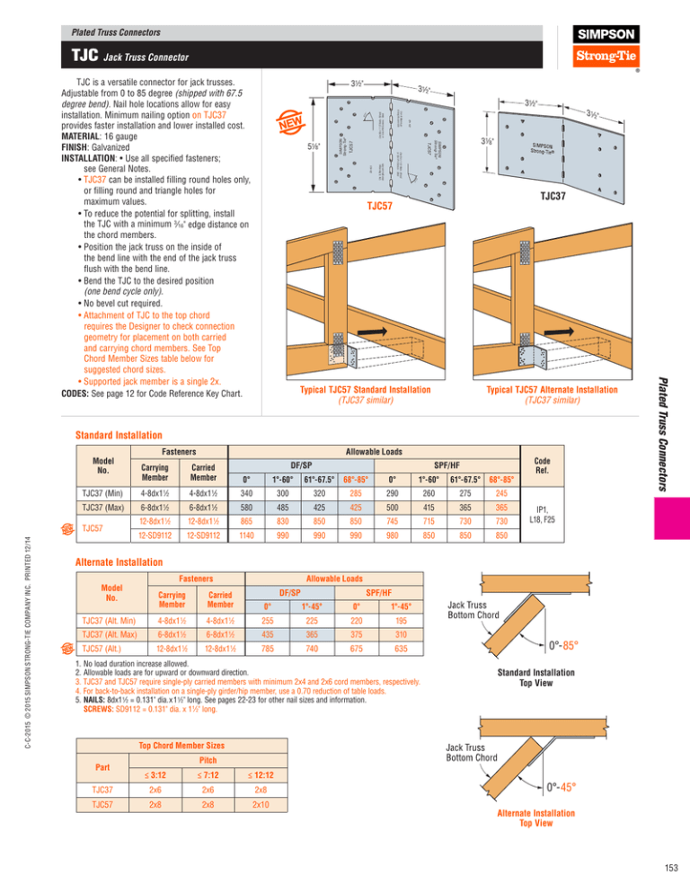
Plated Truss Connectors TJC Jack Truss Connector 31⁄2" 31⁄2" 31⁄2" Use 8d x 1 1/2 Nails - Wood or Use #10 Screws - Steel 67 .5° 67 .5° Use & Warnings: strongtie.com/info ER-102 TJC57 31⁄8" SIMPSON Strong-Tie ® TJC57 Use 8d x 1 1/2 Nails - Wood or Use #10 Screws - Steel SIMPSON Strong-Tie® ER-102 Use & Warnings: strongtie.com/info 51⁄8" 31⁄2" TJC37 TJC57 Typical TJC57 Standard Installation (TJC37 similar) Typical TJC57 Alternate Installation (TJC37 similar) TJC57IN TJC57IN Standard Installation Model No. Allowable Loads DF/SP SPF/HF Carrying Member Carried Member 0° 1°-60° 61°-67.5° 68°-85° 0° 1°-60° 61°-67.5° 68°-85° TJC37 (Min) 4-8dx1 1⁄2 4-8dx1 1⁄2 340 300 320 285 290 260 275 245 TJC37 (Max) TJC57 C-C-2015 © 2015 SIMPSON STRONG-TIE COMPANY INC. PRINTED 12/14 Fasteners 6-8dx1 ⁄2 6-8dx1 ⁄2 580 485 425 425 500 415 365 365 12-8dx1 1⁄2 12-8dx1 1⁄2 865 830 850 850 745 715 730 730 12-SD9112 12-SD9112 1140 990 990 990 980 850 850 850 1 1 Code Ref. Plated Truss Connectors TJC is a versatile connector for jack trusses. Adjustable from 0 to 85 degree (shipped with 67.5 degree bend). Nail hole locations allow for easy installation. Minimum nailing option on TJC37 provides faster installation and lower installed cost. MATERIAL: 16 gauge FINISH: Galvanized INSTALLATION: • Use all specified fasteners; see General Notes. • TJC37 can be installed filling round holes only, or filling round and triangle holes for maximum values. • To reduce the potential for splitting, install the TJC with a minimum 3⁄16" edge distance on the chord members. • Position the jack truss on the inside of the bend line with the end of the jack truss flush with the bend line. • Bend the TJC to the desired position (one bend cycle only). • No bevel cut required. • Attachment of TJC to the top chord requires the Designer to check connection geometry for placement on both carried and carrying chord members. See Top Chord Member Sizes table below for suggested chord sizes. • Supported jack member is a single 2x. CODES: See page 12 for Code Reference Key Chart. IP1, L18, F25 Alternate Installation Model No. Fasteners Allowable Loads DF/SP SPF/HF Carrying Member Carried Member 0° 1°-45° 0° 1°-45° TJC37 (Alt. Min) 4-8dx1 1⁄2 4-8dx1 1⁄2 255 225 220 195 TJC37 (Alt. Max) 6-8dx1 1⁄2 6-8dx1 1⁄2 435 365 375 310 TJC57 (Alt.) 12-8dx1 1⁄2 12-8dx1 1⁄2 785 740 675 635 1.No load duration increase allowed. 2.Allowable loads are for upward or downward direction. 3. TJC37 and TJC57 require single-ply carried members with minimum 2x4 and 2x6 cord members, respectively. 4. For back-to-back installation on a single-ply girder/hip member, use a 0.70 reduction of table loads. 5.NAILS: 8dx1 1⁄2 = 0.131" dia. x 1 1⁄2" long. See pages 22-23 for other nail sizes and information. SCREWS: SD9112 = 0.131" dia. x 1 1⁄2" long. 0°-85° Standard Installation Top View TJC57IN_TopView Top Chord Member Sizes Part Pitch ≤ 3:12 ≤ 7:12 ≤ 12:12 TJC37 2x6 2x6 2x8 TJC57 2x8 2x8 2x10 0°-45° Alternate Installation Top View TJC57IN_TopView 153


