Technical Data 4312
Effective October 2015
Supersedes March 2007
CMT
Common mode inductors, through-hole
Applications
•
Protects AC input from effects of switching
regulators
•
Off-line power supplies
•
EMI filters
•
DC-DC converters
•
Computer, TV, audio and office equipment
Environmental data
Product description
•
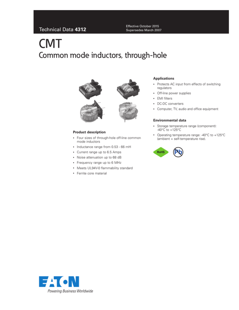
Four sizes of through-hole off-line common
mode inductors
•
Inductance range from 0.53 - 66 mH
•
Current range up to 6.5 Amps
•
Noise attenuation up to 68 dB
•
Frequency range up to 6 MHz
•
Meets UL94V-0 flammability standard
•
Ferrite core material
•
Storage temperature range (component):
-40°C to +125°C
•
Operating temperature range: -40°C to +125°C
(ambient + self-temperature rise).
Pb
CMT
Common mode inductors, through-hole
Technical Data 4312
Effective October 2015
Product specifications
Part number
OCL (mH)
minimum (1-2)
OCL (mH)
minimum (4-3)
l rms.
Amperes max
DCR (Ω) typ
@ 20°C (1-2)
DCR (Ω) typ
@ 20°C (4-3)
CMT1-1-R
66.0
66.0
0.74
1.20
1.20
CMT1-2-R
49.0
49.0
0.88
0.85
0.85
CMT1-3-R
28.0
28.0
1.13
0.50
0.50
CMT1-4-R
21
21
1.37
0.35
0.35
CMT1-5-R
13
13
1.76
0.20
0.20
CMT1-6-R
7.50
7.50
2.27
0.13
0.13
CMT1-7-R
4.20
4.20
2.89
0.08
0.08
CMT1-8-R
2.40
2.40
3.85
0.045
0.045
CMT1-9-R
1.85
1.85
4.53
0.033
0.033
CMT1-10-R
0.94
0.94
6.05
0.018
0.018
CMT2-1-R
30
30
1.50
0.350
0.350
CMT2-2-R
20
20
1.95
0.220
0.220
CMT2-3-R
12
12
2.45
0.135
0.135
CMT2-4-R
8.0
8.0
2.80
0.100
0.100
CMT2-5-R
6.0
6.0
3.40
0.070
0.070
CMT2-6-R
4.8
4.8
3.95
0.053
0.053
CMT2-7-R
3.2
3.2
4.40
0.042
0.042
CMT2-8-R
2.4
2.4
4.75
0.037
0.037
CMT2-9-R
2.0
2.0
5.45
0.028
0.028
CMT2-10-R
1.6
1.6
5.75
0.026
0.026
CMT3-1-R
5.4
5.4
2.0
0.12
0.12
CMT3-2-R
3.5
3.5
2.6
0.08
0.08
CMT3-3-R
2.7
2.7
3.0
0.055
0.055
CMT3-4-R
1.3
1.3
4.0
0.032
0.032
CMT3-5-R
0.92
0.92
5.0
0.021
0.021
CMT3-6-R
0.53
0.53
6.5
0.013
0.013
CMT4-1-R
5.4
5.4
2.0
0.12
0.12
CMT4-2-R
3.5
3.5
2.6
0.08
0.08
CMT4-3-R
2.7
2.7
3.0
0.055
0.055
CMT4-4-R
1.3
1.3
4.0
0.032
0.032
CMT4-5-R
0.92
0.92
5.0
0.021
0.021
CMT4-6-R
0.53
0.53
6.5
0.013
0.013
Definitions:
OCL = Open Circuit Inductance
DCR = Direct Current Resistance
Irms = rms current for 40°C max temperature rise at worst case ambient temperature
of 85°C.
2
www.eaton.com/elx
Electrical Characteristics:
OCL (1-2) 0.10Vrms, 10kHz, 0.0Adc: (See Chart)
OCL (4-3) 0.10Vrms, 10kHz, 0.0Adc: (See Chart)
DCR (1-2) typ @ 20°C: (See Chart)
DCR (4-3) typ @ 20°C: (See Chart)
Hipot rating: winding to winding: 2400 Vac for 1 second. Turns Ratio: (1-2):(4-3) 1:1
CMT
Common mode inductors, through-hole
Technical Data 4312
Effective October 2015
Dimensions–mm
CMT1
FRONT VIEW
SIDE VIEW
29.5 max
CMT1-X
wwll yy R
BOTTOM VIEW
RECOMMENDED PCB LAYOUT
SCHEMATIC
0.80 dia
1.15 dia ± 0.13
4
1
2
3
1
4
36.5 max
2
3
13.0 ± 0.20
3
3
2
3
Pin #1 indicator
3.8
typ
2
4
22.0 max
component side
10.0 ± 0.20
1
4
10.00
13.00
CMT2
FRONT VIEW
SIDE VIEW
36.5 max
CMT2 wwll yy R
RECOMMENDED PCB LAYOUT
BOTTOM VIEW
3.00 dia ± 0.13
15.0
± 0.20
44.5 max
2
3
3
21.0 ±0.2
CMT3
TOP VIEW
1
5
typ
2
15.0
±0.20
3
15.0
±0.20
3
3
4
ØDia
1
1
y dia
4
2
25.0 max Dia
3
RECOMMENDED PCB LAYOUT
BOTTOM VIEW
SIDE VIEW
Pin #1 Indicator
2
Pin #1 indicator
21.0 ± 0.20
4
15.0
±0.2
4
26.5 max
4
1
3
2
1
3
2
component side
3.2
4.0
± 1.0
1.2 dia
4
1
SCHEMATIC
15.0
± 0.20
2
z dia
CMT3-1
CMT3-2
CMT3-3
CMT3-4
CMT3-5
CMT3-6
component side
3
4
2
"Y" Dia
ref
0.58
0.64
0.71
0.80
0.89
0.99
"Z" Dia ref
0.83
0.90
0.97
1.06
1.15
1.25
15.0 ± 0.20
14 max
CMT4
FRONT VIEW
BOTTOM VIEW
SIDE VIEW
4
5.0 typ
1
Pin #1 indicator
12.00
1
3
2
1
y dia
1
CMT4-x
wwllyy - R
25.5 max
4
RECOMMENDED PCB LAYOUT
15.4 max
25.0 max
11.00
11.0
± 0.20
z dia
4
component side
2
3
CMT4-1
CMT4-2
CMT4-3
CMT4-4
CMT4-5
CMT4-6
"Y" Dia
ref
0.58
0.64
0.71
0.80
0.89
0.99
"Z" Dia ref
0.83
0.90
0.97
1.06
1.15
1.25
12.0 ± 0.20
2
(1) All Dimensions are in millimeters unless otherwise
specified
(2) Tolerances are +/- 0.20mm unless stated otherwise.
(3) wwllyy = (Date Code) R = (Revision Level)
Schematic is the same for all the series
www.eaton.com/elx
3
CMT
Common mode inductors, through-hole
Technical Data 4312
Effective October 2015
Attenuation Curves
Attenuation CMT1
0
-6 -7 -8 -9
-10
-10
dB
-20
-30
-40
-50
-60
-1 -2 -3
-70
0.06
0.1
-4 -5
0.2
0.6
1
2
4
FREQUENCY (MHz)
dB
Attenuation CMT2
-20
-25
-30
-35
-40
-45
-50
-55
-60
-65
-70
-6
-7 -8
-9
-10
-1 -2 -3 -4 -5
0.08
0.1
0.15
0.2
0.3
0.4
0.5
0.6
0.7
0.8
4
6
FREQUENCY (MHz)
Attenuation CMT3 & CMT4
-10
-15
-5
-20
-6
dB
-25
-30
-3
-35
-4
-40
-45
-50
0.06
-1
0.1
-2
0.2
0.4
0.6
0.8
1
FREQUENCY (MHz)
4
www.eaton.com/elx
2
CMT
Common mode inductors, through-hole
Technical Data 4312
Effective October 2015
Impedance Curves
Impedance
100
CMT1 - 1 thru - 5
-1
90
-2
80
18
Z (K Ohm)
50
40
30
-4
10
0.1
0.2
0.3
0.4
0.5
0.6
0.7
0.8
-5
0.2
0.3
0.4
0.5
0.6
-8
15
10
-9
0.05 0.1 0.2 0.3 0.4 0.5 0.6 0.7 0.8 0.9
1.2 1.4 1.6
Impedance CMT3 & CMT4
3.5
-1
-3
3
-4 -5
-6
2.5
-2
Z (K Ohm)
Z (K Ohm)
1
FREQUENCY (MHz)
25
10
5
2
1.5
1
0.5
0
0.06
-10
0
0.7
Impedance CMT3 & CMT4
15
1.4
-7
FREQUENCY (MHz)
20
1
CMT2 - 6 thru -10
-6
5
20
0.1
0.8
20
-4
40
0.05
0.6
Impedance
-1
-3
0.4
FREQUENCY (MHz)
25
60
0
0.2
CMT2 - 1 thru - 5
-2
-9
6
0.05
0.9
Z (K Ohm)
Z (K Ohm)
80
10
8
2
FREQUENCY (MHz)
Impedance
-10
-8
0
0.05
100
12
4
-5
0
120
-7
14
60
20
CMT1 - 6 thru -10
-6
16
-3
70
Z (K Ohm)
Impedance
20
0.1
0.2
0.4
0.6
FREQUENCY (MHz)
0.8
1
2
0
0.06
0.1
0.2
0.4
0.6
0.8
FREQUENCY (MHz)
1
2
4
www.eaton.com/elx
5
CMT
Common mode inductors, through-hole
Technical Data 4312
Effective October 2015
Wave solder profile
tp
Temperature
Tp
First Wave
Second Wave
Tsmax
Tstyp
Tsmin
Preheat area
Cool down area
Time
Reference EN 61760-1:2006
Profile Feature
Standard SnPb Solder
Lead (Pb) Free Solder
• Temperature min. (Tsmin)
100°C
100°C
• Temperature typ. (Tstyp)
120°C
120°C
• Temperature max. (Tsmax)
130°C
130°C
• Time (Tsmin to Tsmax) (ts)
70 seconds
70 seconds
D preheat to max Temperature
150°C max.
150°C max.
Peak temperature (TP)*
235°C – 260°C
250°C – 260°C
Time at peak temperature (tp)
10 seconds max
5 seconds max each wave
10 seconds max
5 seconds max each wave
Ramp-down rate
~ 2 K/s min
~3.5 K/s typ
~5 K/s max
~ 2 K/s min
~3.5 K/s typ
~5 K/s max
Time 25°C to 25°C
4 minutes
4 minutes
Preheat
Manual solder
350°C, 4-5 seconds. (by soldering iron), generally manual, hand soldering is not recommended.
Life Support Policy: Eaton does not authorize the use of any of its products for use in life support devices or systems without the express written
approval of an officer of the Company. Life support systems are devices which support or sustain life, and whose failure to perform, when properly
used in accordance with instructions for use provided in the labeling, can be reasonably expected to result in significant injury to the user.
Eaton reserves the right, without notice, to change design or construction of any products and to discontinue or limit distribution of any products. Eaton also
reserves the right to change or update, without notice, any technical information contained in this bulletin.
Eaton
Electronics Division
1000 Eaton Boulevard
Cleveland, OH 44122
United States
www.eaton.com/elx
© 2015 Eaton
All Rights Reserved
Printed in USA
Publication No. 4312
October 2015
Eaton is a registered trademark.
All other trademarks are property
of their respective owners.


