PolySwitch®
PTC Devices
PRODUCT: microSMD250LR-A-2
Overcurrent Protection Device
DOCUMENT: SCD28261
REV LETTER: F
REV DATE: JUNE 2, 2016
PAGE NO.: 1 OF 2
Specification Status: Released
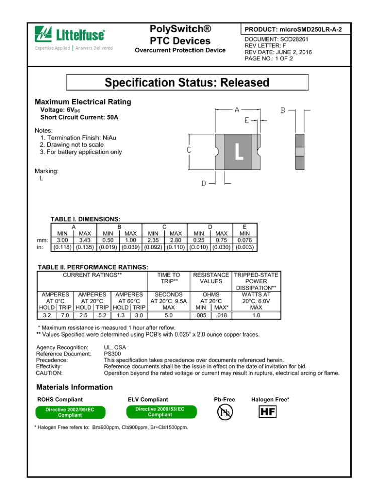
Maximum Electrical Rating
Voltage: 6VDC
Short Circuit Current: 50A
Notes:
1. Termination Finish: NiAu
2. Drawing not to scale
3. For battery application only
Marking:
L
TABLE I. DIMENSIONS:
A
B
C
D
E
MIN
MAX
MIN
MAX
MIN
MAX
MIN
MAX
MIN
mm:
3.00
3.43
0.50
1.00
2.35
2.80
0.25
0.75
0.076
in:
(0.118) (0.135) (0.019) (0.039) (0.092) (0.110) (0.010) (0.030) (0.003)
TABLE II. PERFORMANCE RATINGS:
CURRENT RATINGS**
TIME TO
TRIP**
AMPERES
AMPERES
AMPERES
SECONDS
AT 0°C
AT 20°C
AT 60°C
AT 20°C, 9.5A
HOLD TRIP HOLD TRIP HOLD TRIP
MAX
3.2
7.0
2.5
5.2
1.3
3.0
5.0
RESISTANCE TRIPPED-STATE
VALUES
POWER
DISSIPATION**
OHMS
WATTS AT
AT 20°C
20°C, 6.0V
MIN MAX*
MAX
.005
.018
1.0
* Maximum resistance is measured 1 hour after reflow.
** Values Specified were determined using PCB’s with 0.025” x 2.0 ounce copper traces.
Agency Recognition:
Reference Document:
Precedence:
Effectivity:
CAUTION:
UL, CSA
PS300
This specification takes precedence over documents referenced herein.
Reference documents shall be the issue in effect on the date of invitation for bid.
Operation beyond the rated voltage or current may result in rupture, electrical arcing or flame.
Materials Information
ROHS Compliant
ELV Compliant
Pb-Free
Halogen Free*
HF
* Halogen Free refers to: Br≤900ppm, Cl≤900ppm, Br+Cl≤1500ppm.
PolySwitch®
PTC Devices
Overcurrent Protection Device
PRODUCT: microSMD250LR-A-2
DOCUMENT: SCD28261
REV LETTER: F
REV DATE: JUNE 2, 2016
PAGE NO.: 2 OF 2
Recommended pad layout (mm.)
2.00
2.65
1.00
1.00
Recommended reflow profile
Profile Feature
Average ramp up rate (Tsmax to
Tp)
Preheat
• Temperature min. (Tsmin)
• Temperature max. (Tsmax)
• Time (tsmin to tsmax)
Time maintained above:
• Temperature (TL)
• Time (tL)
Peak/Classification
temperature (Tp)
Time within 5°C of actual peak
temperature (tp)
Ramp down rate
Time 25°C to peak temperature
Pb-Free
Assembly
3°C/s max.
150°C
200°C
60-120s
217°C
60-150s
260°C
30s max.
2°C/s max.
8 mins max.
Note: All temperatures refer to top side of the package, measured on the package body surface.
Solder reflow recommendation
Recommended reflow methods: IR, hot air and Nitrogen
Recommended maximum solder paste thickness: 0.25mm
Recommended minimum stencil thickness: 0.1mm
Devices can be cleaned using standard methods and aqueous solvents.
Littelfuse believes the optimum conditions for forming acceptable solder fillets occur when a reasonable
amount of solder paste is placed underneath each device's termination. As such, we request that customers
comply with our recommended solder pad layouts.
Customer should validate that the solder paste amount and reflow recommendations meet its application.
Littelfuse requests that customer board layouts refrain from placing raised features (e.g. vias, nomenclature,
traces, etc.) underneath PolySwitch devices. It is possible that raised features could negatively impact
solderability performance of our devices.
© 2012, 2016 Littelfuse Inc. All rights reserved.

