Technical Data
1756 ControlLogix Chassis Specifications
Standard Catalog Numbers 1756-A4, 1756-A7,
1756-A10, 1756-A13, 1756-A17
ControlLogix-XT Catalog Numbers 1756-A5XT,
1756-A7LXT
Topic
Page
1756 Standard Chassis
2
1756 ControlLogix-XT Chassis
4
1756 Chassis Accessories
5
Spacing Requirements
6
Standard Mounting Dimensions
7
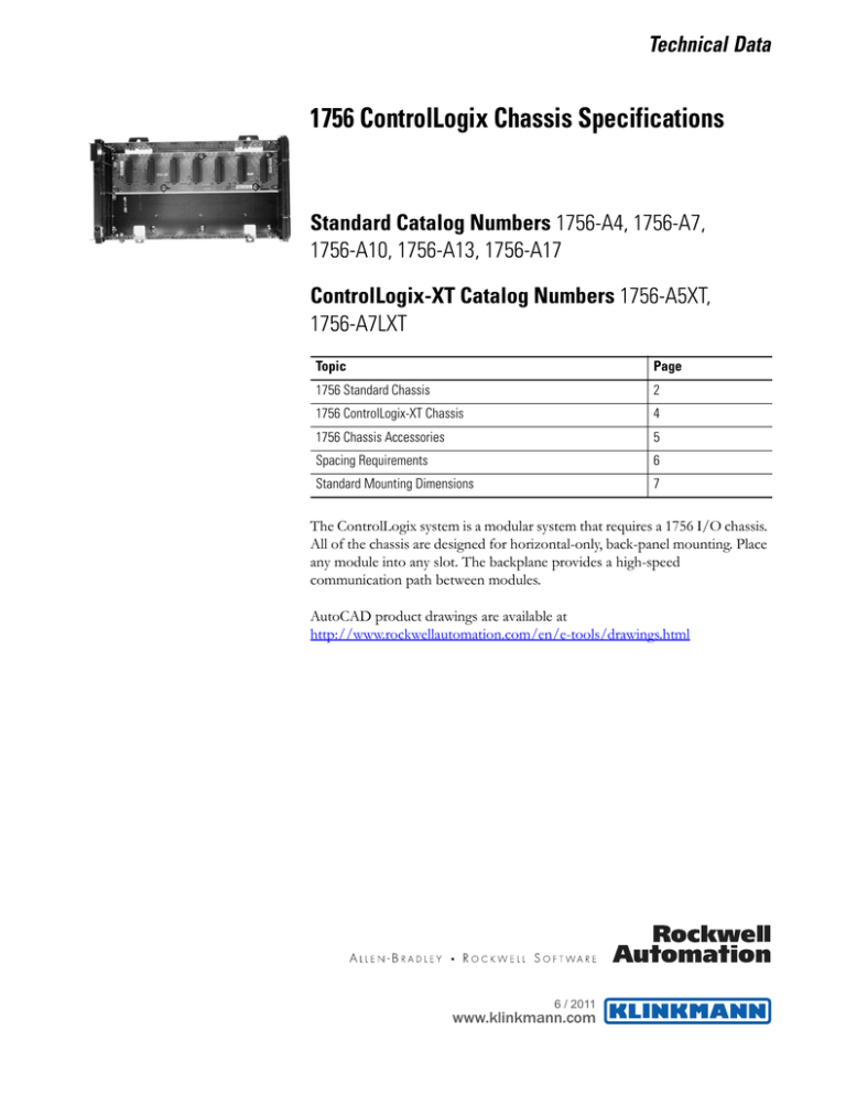
The ControlLogix system is a modular system that requires a 1756 I/O chassis.
All of the chassis are designed for horizontal-only, back-panel mounting. Place
any module into any slot. The backplane provides a high-speed
communication path between modules.
AutoCAD product drawings are available at
http://www.rockwellautomation.com/en/e-tools/drawings.html
6 / 2011
www.klinkmann.com
6 / 2011
www.klinkmann.com
1756 ControlLogix Chassis Specifications
The chassis backplane provides a high-speed communication path between
modules and distributes power to each of the modules within the chassis.
1756 Standard Chassis
Environmental Specifications - 1756 Standard Chassis
Attribute
1756-A4, 1756-A7, 1756-A10, 1756-A13, 1756-A17
Temperature, operating
IEC 60068-2-1 (Test Ad, Operating Cold),
IEC 60068-2-2 (Test Bd, Operating Dry Heat),
IEC 60068-2-14 (Test Nb, Operating Thermal Shock)
0…60 °C (32…140 °F)
Temperature, storage
IEC 60068-2-1 (Test Ab, Unpackaged Nonoperating Cold),
IEC 60068-2-2 (Test Bb, Unpackaged Nonoperating Dry Heat),
IEC 60068-2-14 (Test Na, Unpackaged Nonoperating Thermal Shock)
-40…85 °C (-40…185 °F)
Relative humidity
IEC 60068-2-30 (Test Db, Unpackaged Nonoperating Damp Heat)
5…95% noncondensing
Vibration
IEC 60068-2-6 (Test Fc, Operating)
2 g @ 10…500 Hz
Shock, operating
IEC 60068-2-27 (Test Ea, Unpackaged Shock)
30 g
Shock, nonoperating
IEC 60068-2-27 (Test Ea, Unpackaged Shock)
50 g
Technical Specifications - 1756 Standard Chassis
Attribute
1756-A4
Backplane current, chassis/slot max @
1.2V DC
1.5 A/1.5 A
1756-A7
1756-A10
1756-A13
1756-A17
Backplane current, chassis/slot max @
3.3V DC
4 A/4 A
Backplane current, chassis/slot max @
5.1V DC
15 A/6 A
Backplane current, chassis/slot max @
24V DC
2.8 A/2.8 A
Power dissipation
6.1 BTU/hr
Power consumption
1.8 W
Slots
4
7
10
13
17
263 x 169 x 145 mm
(10.35 x 6.65 x 5.71 in.)
368 x 169 x 145 mm
(14.49 x 6.65 x 5.71 in.)
483 x 169 x 145 mm
(19.0 x 6.65 x 5.71 in.)
588 x 169 x 145 mm
(23.15 x 6.65 x 5.71 in.)
738 x 169 x 145 mm
(29.06 x 6.65 x 5.71 in.)
Cabinet size (WxHxD), min
507 x 507 x 203 mm
(20 x 20 x 8 in.)
507 x 609 x 203 mm
(20 x 24 x 8 in.)
762x 507 x 203 mm
(30 x 20 x 8 in.)
762 x 609 x 203 mm
(30 x 24 x 8 in.)
914 x 762 x 203 mm
(36 x 30 x 8 in.)
Weight, approx.
0.75 kg (1.7 lb)
1.10 kg (2.4 lb)
1.45 kg (3.2 lb)
1.90 kg (4.2 lb)
2.20 kg (4.8 lb)
Location
Panel
North American temperature code
T5
IEC temperature code
T6
Enclosure type rating
None (open-style)
Mounting method
Dimensions (WxHxD), approx.
(1)
2
Horizontal only
(1)
Dimensions include mounting tabs and power supply. Depth with extended terminal housing (1756-TBE) is 160 mm (6.3 in.).
Publication 1756-TD006A-EN-E - May 2009
6 / 2011
www.klinkmann.com
1756 ControlLogix Chassis Specifications
Certifications - 1756 Standard Chassis
Certification(1)
1756-A4, 1756-A7, 1756-A10, 1756-A13, 1756-A17
c-UL-us
UL Listed Industrial Control Equipment, certified for US and Canada. See UL File E65584.
UL Listed for Class I, Division 2 Group A,B,C,D Hazardous Locations, certified for U.S. and Canada. See UL File
E194810.
CSA
CSA Certified Process Control Equipment. See CSA File LR54689C.
CSA Certified Process Control Equipment for Class I, Division 2 Group A,B,C,D Hazardous Locations. See CSA File
LR69960C.
ATEX
European Union 94/9/EC ATEX Directive, compliant with:
EN 60079-15; Potentially Explosive Atmospheres, Protection “n” (Zone 2)
CE
European Union 2004/108/IEC EMC Directive, compliant with:
• EN 61326-1; Meas./Control/Lab., Industrial Requirements
• EN 61000-6-2; Industrial Immunity
• EN 61000-6-4; Industrial Emissions
• EN 61131-2; Programmable Controllers (Clause 8, Zone A & B)
C-Tick
Australian Radiocommunications Act, compliant with:
AS/NZS CISPR 11; Industrial Emissions
FM
FM Approved Equipment for use in Class I Division 2 Group A,B,C,D Hazardous Locations
TÜV
TÜV Certified for Functional Safety: up to and including SIL 2
(1)
When marked. See the Product Certification link at http://www.ab.com for Declarations of Conformity, Certificates, and other certification details.
Publication 1756-TD006A-EN-E - May 2009
3
6 / 2011
www.klinkmann.com
1756 ControlLogix Chassis Specifications
The ControlLogix-XT products include control and communication system
components that, when used with FLEX I/O-XT products, provide a
complete control system solution that can be used in environments where
temperatures range from -20...70 °C (-4...158 °F).
1756 ControlLogix-XT
Chassis
When used independently, the ControlLogix-XT system can withstand
environments where the temperature ranges from -25...70 °C (-13...158 °F).
Environmental Specifications - 1756 ControlLogix-XT Chassis
Attribute
1756-A5XT, 1756-A7LXT
Temperature, operating
IEC 60068-2-1 (Test Ad, Operating Cold),
IEC 60068-2-2 (Test Bd, Operating Dry Heat),
IEC 60068-2-14 (Test Nb, Operating Thermal Shock)
-25…70 °C (-13…158 °F)
Temperature, storage
IEC 60068-2-1 (Test Ab, Unpackaged Nonoperating Cold),
IEC 60068-2-2 (Test Bb, Unpackaged Nonoperating Dry Heat),
IEC 60068-2-14 (Test Na, Unpackaged Nonoperating Thermal Shock)
-40…85 °C (-40…185 °F)
Relative humidity
IEC 60068-2-30 (Test Db, Unpackaged Nonoperating Damp Heat)
5...95% noncondensing
Vibration
IEC 60068-2-6 (Test Fc, Operating)
2 g at 10…500 Hz
Shock, operating
IEC 60068-2-27 (Test Ea, Unpackaged Shock)
30 g
Shock, nonoperating
IEC 60068-2-27 (Test Ea, Unpackaged Shock)
50 g
Technical Specifications - 1756 ControlLogix-XT Chassis
Attribute
1756-A5XT
Backplane current, chassis/slot max @ 1.2V DC
1.5 A/1.5 A
Backplane current, chassis/slot max @ 3.3V DC
4 A/4 A
Backplane current, chassis/slot max @ 5.1V DC
15 A/6 A
Backplane current, chassis/slot max @ 24V DC
2.8 A/2.8 A
Power dissipation
17 BTU/hr
Power consumption
5W
Slots
5
Mounting method
7
Horizontal only
158 x 483 x 145 mm
(6.22 x 19 x 5.71 in.)
158 x 368 x 145 mm
(6.22 x 14.49 x 5.71 in.)
Cabinet size (WxHxD), min
507 x 507 x 203 mm (20 x 20 x 8
in.)
507 x 609 x 203 mm (20 x 24 x 8
in.)
Weight, approx.
1.45 kg (3.2 lb)
1.1 kg (2.4 lb)
Location
Panel
Enclosure type rating
None (open-style)
Dimensions (WxHxD), approx.
(1)
4
756-A7LXT
(1)
Dimensions include mounting tabs and power supply. Depth with extended terminal housing (1756-TBE) is 160 mm (6.3 in.).
Publication 1756-TD006A-EN-E - May 2009
6 / 2011
www.klinkmann.com
1756 ControlLogix Chassis Specifications
Certifications - ControlLogix-XT Chassis
Certification(1)
1756-A5XT, 1756-A7LXT
c-UL-us
UL Listed Industrial Control Equipment, certified for US and Canada. See UL File E65584.
UL Listed for Class I, Division 2 Group A,B,C,D Hazardous Locations, certified for U.S. and Canada. See UL File
E194810.
ATEX
European Union 94/9/EC ATEX Directive, compliant with:
EN 60079-15; Potentially Explosive Atmospheres, Protection “n” (Zone 2)
CE
European Union 2004/108/EC EMC Directive, compliant with:
• EN 61000-6-4; Industrial Emissions
• EN 61326-1; Meas./Control/Lab., Industrial Requirements
• EN 61000-6-2; Industrial Immunity
• EN 61131-2; Programmable Controllers (Clause 8, Zone A & B)
C-Tick
Australian Radiocommunications Act, compliant with: AS/NZS CISPR 11; Industrial Emissions
(1)
When marked. See the Product Certification link at http://www.ab.com for Declarations of Conformity, Certificates, and other certification details.
1756 Chassis Accessories
Publication 1756-TD006A-EN-E - May 2009
Use a slot filler module to fill empty slots.
Cat. No.
Description
1756-N2
Slot filler module for empty slots in standard
ControlLogix chassis
1756-N2XT
Slot filler module for empty slots in ControlLogix-XT
chassis
5
6 / 2011
www.klinkmann.com
1756 ControlLogix Chassis Specifications
Spacing Requirements
When you mount a chassis with a standard power supply in an enclosure, meet
these spacing requirements.
Enclosure
15.3 cm (6.0 in.)
10.2 cm
(4.00 in.)
10.2 cm
(4.00 in.)
15.3…20 cm (6.0…8.0 in.)
5.1 cm (2.0 in.)
Wireway
5.1 cm (2.0 in.)
15.3 cm (6.0 in.)
7.7…10.2 cm
(3.0…4.0 in.)
If you use a 1756-PSCA2 chassis adapter with a redundant power supply,
follow the same spacing requirements as for a standard power supply. You
need the clearance on the left of the chassis for cable access.
Enclosure
1756-PA75R or
1756-PB75R
1756-PA75R or
1756-PB75R
15.3...20 cm
(6.0...8.0 in.)
ControlLogix with
1756-PSCA2
> 10.2 cm
(4.0 in.)
6
> 15.3 cm
(6.0 in.)
> 10.2 cm
(4.0 in.)
Publication 1756-TD006A-EN-E - May 2009
6 / 2011
www.klinkmann.com
Standard Mounting
Dimensions
1756 ControlLogix Chassis Specifications
Right-side View of Standard Chassis
16.9 cm
(6.65 in.)
1756-TBE
Extended Housing
14.5 cm
(5.8 in.)
16.0 cm
(6.3 in.)
1756-A4 with Power Supply
1.1 cm
(0.433 in.)
7.0 cm
(2.76 in.)
16.9 cm
(6.65 in.)
15.8 cm
(6.22 in.)
14.5 cm
(5.71 in.)
0.55 cm
(0.217 in.)
4.5 cm
(1.77 in.)
26.3 cm
(10.35 in.)
18.54 cm
(7.30 in.)
Publication 1756-TD006A-EN-E - May 2009
0.55 cm
(0.217 in.)
0.78 cm
(0.31 in.)
Dimension with 1756-PSCA2
7
6 / 2011
www.klinkmann.com
1756 ControlLogix Chassis Specifications
1756-A7 with Power Supply
1.1 cm
(0.433 in.)
17.5 cm
(6.89 in.)
0.55 cm
(0.217 in.)
16.9 cm
(6.65 in.)
15.8 cm
(6.22 in.)
14.5 cm
(5.71 in.)
0.55 cm
(0.217 in.)
36.8 cm
(14.48 in.)
4.7 cm
(1.85 in.)
29.04 cm
(11.44 in.)
0.78 cm
(0.31 in.)
Dimension with 1756-PSCA2
1756-A10 with Power Supply
0.55 cm
(0.217 in.)
1.1 cm
(0.433 in.)
14.0 cm
(5.51 in.)
14.0 cm
(5.51 in.)
5.71 cm
(2.25 in.)
16.9 cm
(6.65 in.)
14.5 cm
(5.71 in.)
15.8 cm
(6.22 in.)
0.55 cm
(0.217 in.)
0.78 cm
(0.31 in.)
48.8 cm
(19.02 in.)
40.54 cm
(15.96 in.)
Dimension with 1756-PSCA2
1756-A13 with Power Supply
0.55 cm
(0.217 in.)
1.1 cm
(0.433 in.)
14.0 cm
(5.51 in.)
10.5 cm
(4.13 in.)
5.71 cm
(2.25 in.)
16.9 cm
(6.65 in.)
14.5 cm
(5.71 in.)
15.8 cm
(6.22 in.)
0.55 cm
(0.217 in.)
58.8 cm
(23.15 in.)
51.04 cm
(20.10 in.)
8
14.0 cm
(5.51 in.)
0.78 cm
(0.31 in.)
Dimension with 1756-PSCA2
Publication 1756-TD006A-EN-E - May 2009
6 / 2011
www.klinkmann.com
1756 ControlLogix Chassis Specifications
1756-A17 with Power Supply
0.55 cm
(0.217 in.)
1.1 cm
(0.433 in.)
14.0 cm
(5.51 in.)
13.3 cm
(5.24 in.)
13.3 cm
(5.24 in.)
14.0 cm
(5.51 in.)
4.7 cm
(1.85 in.)
16.9 cm
(6.65 in.)
14.5 cm
(5.71 in.)
15.8 cm
(6.22 in.)
0.78 cm
(0.31 in.)
73.8 cm
(29.06 in.)
Dimension with 1756-PSCA2
66.04 cm
(26.0 in.)
XT Mounting Dimensions
Right-side View of XT Chassis
16.9
(6.65)
14.5
(5.71)
Publication 1756-TD006A-EN-E - May 2009
9
1756 ControlLogix Chassis Specifications
1756-A5XT with Power Supply
5.71
(2.25)
14.0
(5.51)
14.0
(5.51)
16.9
(6.65)
14.5
(5.71)
15.8
(6.22)
48.3
(19.0)
1756-A7LXT with Power Supply
4.71
(1.85)
17.5
(6.89)
16.9
(6.65)
15.8
(6.22)
14.5
(5.71)
36.8
(14.49)
XT Mounting Tab Dimensions
Top Mounting Tab
Bottom Mounting Tab
0.55
(0.217)
1.1
(0.433)
Publication 1756-TD006A-EN-E - May 2009
Copyright © 2009 Rockwell Automation, Inc. All rights reserved. Printed in the U.S.A.
Rockwell_Logic_Programmable_Controllers_ControlLogix_1756_Chassis_en_0611.pdf
www.klinkmann.com
Riga
tel. +371 6738 1617
klinkmann@klinkmann.lv
Helsinki
tel. +358 9 540 4940
automation@klinkmann.fi
St. Petersburg
tel. +7 812 327 3752
klinkmann@klinkmann.spb.ru
Moscow
tel. +7 495 641 1616
moscow@klinkmann.spb.ru
Yekaterinburg
tel. +7 343 376 5393
yekaterinburg@klinkmann.spb.ru
Samara
tel. +7 846 273 95 85
samara@klinkmann.spb.ru
Кiev
tel. +38 044 495 33 40
klinkmann@klinkmann.kiev.ua
Vilnius
tel. +370 5 215 1646
post@klinkmann.lt
Tallinn
tel. +372 668 4500
klinkmann.est@klinkmann.ee
Мinsk
tel. +375 17 200 0876
minsk@klinkmann.com


