mems dc/dc converters for 1d and 2d vibration-to
advertisement
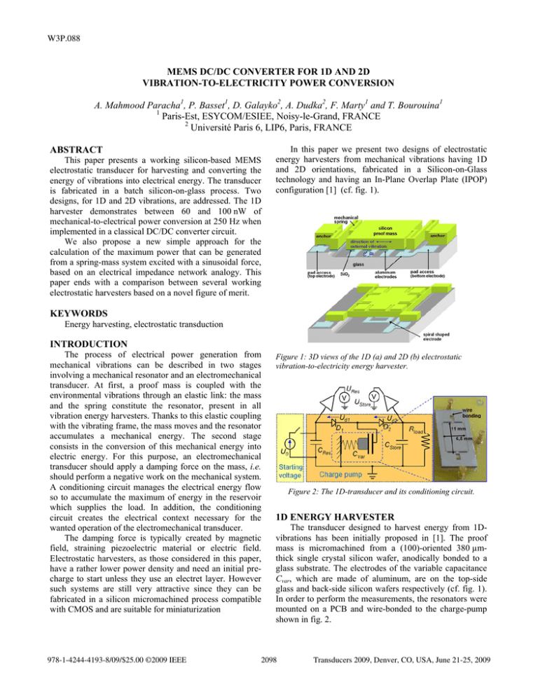
W3P.088 MEMS DC/DC CONVERTER FOR 1D AND 2D VIBRATION-TO-ELECTRICITY POWER CONVERSION A. Mahmood Paracha1, P. Basset1, D. Galayko2, A. Dudka2, F. Marty1 and T. Bourouina1 1 Paris-Est, ESYCOM/ESIEE, Noisy-le-Grand, FRANCE 2 Université Paris 6, LIP6, Paris, FRANCE ABSTRACT This paper presents a working silicon-based MEMS electrostatic transducer for harvesting and converting the energy of vibrations into electrical energy. The transducer is fabricated in a batch silicon-on-glass process. Two designs, for 1D and 2D vibrations, are addressed. The 1D harvester demonstrates between 60 and 100 nW of mechanical-to-electrical power conversion at 250 Hz when implemented in a classical DC/DC converter circuit. We also propose a new simple approach for the calculation of the maximum power that can be generated from a spring-mass system excited with a sinusoidal force, based on an electrical impedance network analogy. This paper ends with a comparison between several working electrostatic harvesters based on a novel figure of merit. In this paper we present two designs of electrostatic energy harvesters from mechanical vibrations having 1D and 2D orientations, fabricated in a Silicon-on-Glass technology and having an In-Plane Overlap Plate (IPOP) configuration [1] (cf. fig. 1). KEYWORDS Energy harvesting, electrostatic transduction INTRODUCTION The process of electrical power generation from mechanical vibrations can be described in two stages involving a mechanical resonator and an electromechanical transducer. At first, a proof mass is coupled with the environmental vibrations through an elastic link: the mass and the spring constitute the resonator, present in all vibration energy harvesters. Thanks to this elastic coupling with the vibrating frame, the mass moves and the resonator accumulates a mechanical energy. The second stage consists in the conversion of this mechanical energy into electric energy. For this purpose, an electromechanical transducer should apply a damping force on the mass, i.e. should perform a negative work on the mechanical system. A conditioning circuit manages the electrical energy flow so to accumulate the maximum of energy in the reservoir which supplies the load. In addition, the conditioning circuit creates the electrical context necessary for the wanted operation of the electromechanical transducer. The damping force is typically created by magnetic field, straining piezoelectric material or electric field. Electrostatic harvesters, as those considered in this paper, have a rather lower power density and need an initial precharge to start unless they use an electret layer. However such systems are still very attractive since they can be fabricated in a silicon micromachined process compatible with CMOS and are suitable for miniaturization 978-1-4244-4193-8/09/$25.00 ©2009 IEEE Figure 1: 3D views of the 1D (a) and 2D (b) electrostatic vibration-to-electricity energy harvester. Figure 2: The 1D-transducer and its conditioning circuit. 1D ENERGY HARVESTER The transducer designed to harvest energy from 1Dvibrations has been initially proposed in [1]. The proof mass is micromachined from a (100)-oriented 380 µmthick single crystal silicon wafer, anodically bonded to a glass substrate. The electrodes of the variable capacitance Cvar, which are made of aluminum, are on the top-side glass and back-side silicon wafers respectively (cf. fig. 1). In order to perform the measurements, the resonators were mounted on a PCB and wire-bonded to the charge-pump shown in fig. 2. 2098 Transducers 2009, Denver, CO, USA, June 21-25, 2009 We applied in-plane vibrations at the proof-mass mechanical resonance frequency of 250 Hz, with a maximum acceleration of 0.25 g to displace the mass by +/- 50 µm. A dynamic measurement of the capacitance variation Cvar is achieved by measuring the phase shift in a RCvar circuit. If a weak voltage is applied on Cvar, it exhibits a variation from 73 to 144 pF. However, when the voltage increases, the vertical electrostatic force between top and bottom electrodes pulls the proof mass down to the substrate, reducing the ratio Cmax/Cmin, mainly because of increase of the fringe field responsible for Cmin value. Thus, at 8 VDC, the measured ratio Cmax/Cmin is 1.3. (cf. fig. 3). This corresponds to a gap reduction of almost 40 %, which is much bigger than the theoretical maximum gap reduction threshold of 33 % for pull-in instability in the case of an ideal electrostatic actuator. This behaviour is ascribed to a nonlinear spring stiffness, which increases at large displacement of the attached proof-mass. electrical energy. Furthermore, energy dissipates in the resistive load and in the diodes. The balance equation for the corresponding electrical power is expressed as: (1) Ph + PCres + PCstore = PRload + Pdiodes , where Ph is the power generated by the mechanical vibrations, PRload and Pdiodes are the power dissipated by the load and the diodes, and PCres and PCstore are the power flows provided by the Cres and Cstore discharges. The power terms are calculated over an interval of time of 6 sec after t0. Details can be found in [2]. These experiments are also modelled using the VHDLAMS model presented in [3], implemented with the same Cmax/Cmin ratio of 1.45 and with a realistic exponential diode model. For the capacitor voltage evolution, the modelling and the experiment agreed better than 3% [2]. We performed experiments with various non-zero loads from 30 to 150 MΩ. The plot in fig. 4 shows the value of Ph, calculated from measured and simulated voltage evolutions. When the power dissipated in the diodes is calculated with Vd = 0.4V/0.6 V assumed constant, we obtain a maximal electrical power generation of 61/103 nW on a 60/50 MΩ load resistor. The power extracted from the modeling experiments highlights a maximal power of 79 nW for an optimal load of 90 MΩ. This discrepancy results from the difficulty to account correctly for the diode losses in the calculation of the experimental power. Figure 3: Measurement of Cvarmax, Cvarmin and Cvarmax/Cvarmin ratio with applied increasing applied DC voltage Figure 5: SEM of the Si-wafer backside just before glass bonding 2D ENERGY HARVESTER Figure 4: Harvested power versus the resistive load Measurement of Converted Power To demonstrate electromechanical energy generation, Cres and Cstore are initially pre-charged with the DC voltage Uo = 6 V, corresponding to approximately half the pull-in voltage. Then the voltage source is switched off at t0 and the system becomes electrically autonomous. Then the electrical network has three energy sources: the discharging capacitors Cres and Cstore, and the capacitive transducer which transforms mechanical energy into In most of cases, the available energy is equally distributed over the three degrees of freedom. Thus, in average, a 2D transducer is twice more efficient than its one-degree of freedom counterparts. The presented design is being inspired from 2-D gyroscope [4]. The net surface area of the device is 1 cm² and resonance frequency is measured at 246 Hz. The patterned electrodes are of a spiral rectangular shape. This is being done to achieve the same capacitance variation in either direction in the plane. The modeled values of max/min capacitances and pull-in voltage are 370 pF / 205 pF and 10 V respectively. Fig. 5 shows a SEM picture of the back side of the proof mass 2099 with the zoomed view of the mechanical springs and the electrodes. The ideal (maximal) value of the power generated by an electrostatic energy harvester using constant-charge triangular QV cycle [7] is given by: ⎛C ⎞ Ph max = U 0 2 C max ⎜ max − 1 ⎟ f elec 2 , ⎝ C min ⎠ (2) where Uo is initial charge voltage which maximum is given by the pull-in voltage times Cmin/Cmax, and felec is the frequency of the transducer capacitance variations. In our transducers, felec is twice the mechanical resonance frequency. Eq. (2) with U0 = 6 V gives 2.6 µW for the theoretical maximal harvested power at the resonance. Figure 6: Equivalent electrical network of a spring-mass vibration energy harvester MAXIMAL POWER GENERATION MODEL Close-form expressions of the maximum power that can be generated from a spring-mass system excited with a sinusoidal force have already been presented in previous papers [5][6]. We present here a different approach using the electrical impedance network analogy. In the mechanical domain, the harvester can be represented by the equivalent electrical network in fig. 6, where m, k, Aext and µm are mass, spring stiffness, acceleration of external vibrations and mechanical damping. In the following, ψe denotes the mechanical impedance of the transducer and ψm the mechanical impedance the resonator which is calculated by m, k and µm. In energy harvesting literature, the electromechanical transducer is often represented by an ideal damper, which has only a real impedance. But, this representation can only be applied to few particular cases (e.g. electromagnetic transduction). In general, the impedance is complex, and should be optimized to estimate the maximal power. From the electromechanical analogy, the power absorbed by a dipole is the real part of the complex power, defined as the half square of module of the current times the impedance of the load. In the mechanical domain, the current is equivalent to the velocity and the mechanical impedance is defined as minus the ratio between the • • complex amplitudes of force ( F ) and velocity ( V ) (dotted letters represents complex quantities). The power harvested from mechanical-to-electrical domains is: 1 •2 (3) Ph = V Re(ψ e ) , 2 • To maximized Ph, both V and Re(ψe) have to be maximized, but there is implicit relation between these two quantities. Let us express this relation. Analyzing the network in fig. 2, we have: • ψ m +ψ e = m Aext , • (4) V Equating the absolute values of both parts and considering Re (ψe) + Re (ψm) positive : 2 ⎛ mAext ⎞ 2 (5) Re(ψ e ) = ⎜ ⎟ − [Im(ψ m + ψ e )] − Re(ψ m ) , ⎝ V ⎠ where V and Aext are modulus of complex values. If we choose ψe so that: (6) Im(ψ e ) = − Im(ψ m ) , thus Re(ψe) is maximized and is linked with V as: mAext (7) Re(ψ e ) = − μm , V Injecting (7) into (3) we get: 1 ⎛ mAext ⎞ 1 (8) Ph = V 2 ⎜ − μ m ⎟ = V (mAext − μ mV ) , 2 ⎝ V ⎠ 2 This expression is maximum when V = 0.5mAext/µm, which gives the expression: 1 2 (9) Ph = (mAext ) μ m , 8 However, in practice, often the mass vibration is limited at Xmax (by the position of the stoppers for instance). If Xmax < 0.5mAext/µm, we are in a so-called “amplitude-constrained” case, and the maximal velocity is V = ωXmax. To maximize the harvested power, the designer should choose this maximal velocity value to get as close as possible to the optimal V. From (8), we have the harvested power: Ph = 1 ⎛ mAext ⎞ 2 − μm ⎟ , X max ω 2 ⎜ 2 ⎝ X maxω ⎠ (10) If µm is negligible as it was supposed in [5], we come to the exactly same formula for Velocity-Damped Resonant Generator (VDRG) having a harmonic motion: 1 1 (11) Ph max = X maxωmAext = X maxω 3 mX ext , 2 2 where Xext is the displacement amplitude of the external vibrations, related with Aext as Aext=Xextω2. CONCLUSION We have shown experimentally the ability to scavenge mechanical vibrations energy in order to provide electrical power to a resistive load, with the use of an electrostatic silicon-based MEMS transducer fabricated in a CMOScompatible technology. This work is the first fully working electrostatic energy harvester fabricated in a silicon batch process without using an electret. The converted power lies between 60 nW and 100 nW, with external vibrations at 250 Hz and an acceleration amplitude of 0.25 g. To make an adequate comparison of our work with 2100 other electrostatic harvesters, we propose a figure of merit (FOM) defined as a normalized converted power: P (12) FOM = 2 h , U fA where Ph is the power converted from the mechanical to the electrical domain, U is the maximal voltage applied on the capacitive transducer, f is the external vibration frequency and A is the device area. Indeed, it is wellrecognized that the output power of capacitive harvesters is proportional to the square of the pre-charge voltage, to the frequency and to the maximal transducer capacitance value. The latter is more or less directly proportional to the device area. The table 2 presents the calculation of this FOM for several published works that have demonstrate effective power conversion; it can be seen that our 1D transducer has one of the best figure of merit. ACKNOWLEDGMENTS This work is partially funded by the French National Research Agency (ANR) through the contract #JC0554551 and is supported by the French competitiveness cluster AdvanCity. REFERENCES [1] P. Lim, P. Basset, A. Mahmood, F. Marty, P. Poulichet, Tarik Bourouina, "Desin of a novel electrostatic MEMS-based vibration-to-electric energy converter based on parallel plates with in plane mechaism", Proceeding of the Asia Pacific Conference on Transducers and Micro-Nano Technology (APCOT’06), 2006 [2] A. Mahmood Paracha, P. Basset, D. Galayko, F. Marty and T. Bourouina, “A MEMS DC/DC Converter for autonomous vibration-to-electrical energy harvester”, to be published in Trans. on Electron Device Letters, 2009 [3] D. Galayko, R. Pizarro, P. Basset, A. Mahmood. Paracha and G. Amendola, "AMS modeling of controlled switch for design optimization of capacitive vibration energy harvester", Proc. of IEEE Int. Behavioral Modeling and Simulation Conf. (BMAS’07), pp. 115-120, 2007 [4] D. Piyabongkarn et al., “Development of a MEMS gyroscope for absolute angle measurement”, IEEE transactions on control systems technology, vol. 13, no. 2, March 2005 [5] P. D. Mitcheson, T. C. Green, E. M. Yeatman and A. S. Holmes, “Architectures for Vibration-Driven Micropower Generators”, IEEE J. of MEMS, vol. 13, no. 3, pp. 429-440, 2004 [6] S. P. Beeby, M. J. Tudor and N. M. White, “Energy harvesting vibration sources for Microsystems applications”, Meas. Sci. Technol., vol. 17, pp. 175195, 2006 [7] S. Meninger, J. O. Mur-Miranda, R. Amirtharajah, A. P. Chadakasan and J. H. Lang, “Vibration-to-electric energy conversion”, IEEE Trans. on Very Large Scale Integration (VLSI) Systems, vol. 9, no. 1, pp. 64-76, 2001 [8] G. Despesse, T. Jager, J. J. Chaillout, J. M. Léger, A. Vassilev, S. Basrour and B. Charlot, “Fabrication and Characterization of High Damping Electrostatic Micro Devices for Vibration Energy Scavenging”, Proc. of DTIP’05, pp. 386-390, 2005 [9] B. C. Yen, H. L. Jeffery, “A variable capacitance vibration-to-electric energy harvester”, IEEE trans. on circuits and systems, vol. 53, no. 2, pp. 288-295, 2006 [10] T. Tsutsumino, Y. Suzuki, N. Kasagi, Y. Sakane, “Seismic Power Generator Using High-Performance Polymer Electret”, Proc. of MEMS ‘06, pp. 98-101, 2006 [11] W. Ma, R. Zhu, L. Rufer, Yitshak Zohar, M. Wong, An Integrated Floating-Electrode Electric Microgenerator, IEEE J. of MEMS, vol. 16 no. 1, 2007 [12] Y. Suzuki, M. Edamoto, N. Kasagi, K. Kashwagi, Y. Morizawa, “Micro Electrets Energy Harvesting Device with Analogue Impedance Conversion Circuit”, Proc. of PowerMEMS’08, pp. 7-10, 2008 CONTACT * P. Basset, tel: +33-1-45926586; p.basset@esiee.fr Table 1: Comparison of electrostatic energy harvesters. Operating Device area Author, [ref.] Year frequency A, [mm2] f, [Hz] G. Despesse et al., [8] 2005 50 1800 B. Yen et al., [9] 2006 1560 4356 T. Tsutsumino et al., [10] 2006 20 200 W. Ma et al., [11] 2007 4100 25.9 Y. Suzuiki et al., [12] 2008 37 900 This work 2009 250 66 1 Operation voltage, [V] 120 6 950 (electret) 15 ( “electret like”) 450 (electret) 8 Converted power Ph , [µW] 1050 9.471 37.7 0.065 0.28 0.061 Figure of merit (FOM) Ph /(U2fA), [108µW/(mm2HzV2)-1] 81 3.9 1.0 0.27 0.0034 5.7 The authors provide only the power delivered to the load (1.8 µW), and they note that the efficiency is about 19 %. Thus, to roughly estimate the converted power, we divided 1.8 µW by. 0.19. 2101
