26 DEVELOPMENT POWER ElECTROniCS
advertisement

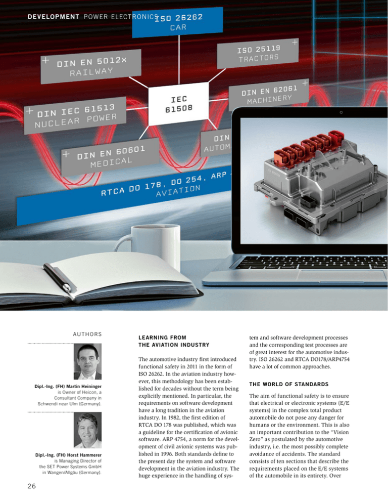
DE VELO PMENT P ower El ectronics AUTHORS Dipl.-Ing. (FH) Martin Heininger is Owner of Heicon, a Consultant Company in Schwendi near Ulm (Germany). Dipl.-Ing. (FH) Horst Hammerer is Managing Director of the SET Power Systems GmbH in Wangen/Allgäu (Germany). 26 LEARNING FROM THE AVIATION INDUSTRY The automotive industry first introduced functional safety in 2011 in the form of ISO 26262. In the aviation industry however, this methodology has been established for decades without the term being explicitly mentioned. In particular, the requirements on software development have a long tradition in the aviation industry. In 1982, the first edition of RTCA DO 178 was published, which was a guideline for the certification of avionic software. ARP 4754, a norm for the development of civil avionic systems was published in 1996. Both standards define to the present day the system and software development in the aviation industry. The huge experience in the handling of sys- tem and software development processes and the corresponding test processes are of great interest for the automotive industry. ISO 26262 and RTCA DO178/ARP4754 have a lot of common approaches. THE WORLD OF STANDARDS The aim of functional safety is to ensure that electrical or electronic systems (E/E systems) in the complex total product automobile do not pose any danger for humans or the environment. This is also an important contribution to the “Vision Zero” as postulated by the automotive industry, i.e. the most possibly complete avoidance of accidents. The standard consists of ten sections that describe the requirements placed on the E/E systems of the automobile in its entirety. Over Testing Power Electronics According to ISO 26262 Increasingly, power electronics are taking on important tasks in safety-relevant applications such as power steering, brakes or electric powertrains. The requirements for functional safety are defined in ISO 26262. A comparison with the long established development and test methods in the aviation industry can help understand these requirements better. In this article, the consulting company Heicon compares the test principles in the automotive industry with those in the aviation industry. Using the e-motor emulators from SET Power Systems, these principles can be implemented in practical situations for the test of e-motor control systems. © Bosch, SET Power Systems and above this, the standard describes requirements placed on the complete product life cycle, for example the third section concentrates on the very early conceptual phase of a product. Section 7 focuses on production, operation (including repair and maintenance) and decommissioning. Sections 4 to 6 are dedicated to the development process of the product. FIGURE 1 shows the structure of the norm ISO 26262. It considers in its structure at least two levels of development. The ­system level (section 4) lies above the software (section 6) and hardware levels (section 5). A classical system, for example, is an electrical drive controller. This power electronic component is part of a larger system in the vehicle, such as the electri 04I2015 Volume 10 cal powertrain. In turn, this constitutes a sub-system of the entire vehicle. Hence a vehicle consists of different sub-systems on different levels. ISO 26262 (section 1) defines the concept “system“ as follows: “A system is a set of elements that relates at least a sensor, a controller and an actuator with one another.” (Note 1: The related sensor or actuator can be included in the system, or can be external to the system, Note 2: An element of a system can also be another system.) Although the functional safety concentrates on the dangers that result from the end product, the norm defines several levels. Each level has a set of defined activities and working products that are to be executed and that must be created. This granularity permits control of the whole system complexity. The sum of the functionally safe individual components leads to a functionally safe complete system. This holistic perspective corresponds to the aviation norms RTCA DO254 (hardware), RTA DO178 (software) and ARP 4754 (systems). EARLIER AND SIMPLER VERIFICATION The verification of a system in the aviation industry has been established for some considerable time and has proven itself on different levels. The advantages seem obvious: The division into different levels permits verification to commence very early on in the development cycle. Less effort is required to locate a fault on lower levels than in complete systems such as an airplane or automobile. 27 DE VELO PMENT P ower El ectronics FIGURE 1 Structure of ISO 26262 with possible verification processes according to the V-model Using the example of the verification of a classic control unit, we focus on the system and software verification. ­F IGURE 2 uses the V-model to show the levels in ISO 26262 that must be verified. The availability of real hardware is at best limited if not non-existent in early stages, for example the e-motor for electric powertrains. This has consequences for the verification of the inverter. Such coupled dependencies quickly lead to problems in the verification loop meaning that important information is only gained at later stages. Such difficulties can be avoided through consequent verification on ­various levels. It also enables further parallelisation of hardware and software FIGURE 2 Advantage aviation: By dividing the complete system into different levels, functional safety can be tested at very early stages of development 28 development. Furthermore, the robustness of individual software elements can be comparably easily tested. Even the stimulation of extreme scenarios is less effort on the software integration or software unit level than on a vehicle level. Many scenarios that can be simulated on lower levels cannot even be ­tested on a vehicle level. The success of such a verification strategy depends on two important prerequisites: The test environment used must be fault-free ­itself and must mirror real operating conditions. Higher integration levels require a wider scope of simulation and emulation. The following tried and trusted principles are employed in the aviation industry for such test environments: –– Software unit tests always use the ­original compiler with identical settings to the operational environment. This requires however that the compiler manufacturers supply simulators or emulators to enable the tests on a host PC. –– It must be possible at any time to prove that the plausibility of a test environment matches real conditions. In ­particular, a proving strategy must be developed that shows that the simulator is correct and adequately reproduces real conditions. Since a tool cannot be qualified “in general”, a qualification of the tools is necessary that considers the peculiarities of each test environment for the qualification. The effort required to do this is limited however, since normally pre-defined tests are available. These “only” have to be repeated in the corresponding project. –– The unit under test cannot be changed. This point is crucially important. The scope of the unit under test naturally depends on the test level. For software tests, the unit under test in extreme cases can consist of a single software function. This function, that is then defined as the unit under test, may not be changed under any circumstances. This is also valid for higher test levels. So for example, this means for the system level test of a drive inverter, the tests must be executed with the original device consisting of hardware and software. Any deviation from the version that will later be built into the vehicle in endangers the meaningfulness of the test and hence for the functional safety. VERIFICATION ON AN INTEGRATION AND SYSTEM LEVEL Often, complex simulations or emulations are necessary on hardware/software integration or system levels in order to guarantee the highest degree of reality in environmental conditions, despite partial integration. Electromotor actuators, as found in today’s power steering, power assisted brakes or complete electric powertrains, are equipped with ­control units, which can be tested with e-motor emulators, FIGURE 3. For example, this test topology permits the component “drive inverter” to be verified separately from the component “e-motor”. The advantages are clear: Lower complexity, since only the elec­ tronic components need to be tested, and de-coupling of dependencies in the project plan. Furthermore, it is not always possible to represent typical fault conditions of an electric motor by using an electric motor directly. E-motor emulation is different: Phase errors, faults in the rotor sensor, adjustment faults, motor tolerances etc. can be stimulated easily. FIGURE 3 shows the layout of such a ­so-called Power Hardware-in-the-Loop (PHiL) setup. Compared to conventional HiL setups using low-signal levels, the use of an emulator for power control units offers many advantages. The unit under test is not changed in any way. Neither do the power paths need to be switched off and modelled; they remain physically present. The unit-under-test is thus in the “original” state – one of the critical prerequisites for meaningful qualification. Such a system setup can reproduce the loads and environmental conditions that occur in real operation on a drive inverter in a laboratory. The elimination of the real motor not only brings with it improved test possibilities and a separation of test tasks, but also “transfers” the test environment into a lab environ- VERIFICATION ON SOFTWARE INTEGRATION AND UNIT LEVEL The software unit and software integration levels have the advantage that no hardware is required. So-called test drivers, or Stubs, simulate the interfaces to the hardware to enable an executable form of the software unit. This has cost and time advantages and enables the functionality and logic of the software in particular to be verified early in the project. Faults are quickly found since only a few software modules need to be considered. On a system level, fault determination is often difficult and associated with great effort: This starts with the question whether a fault is actually software or hardware oriented. Consequential faults must also be considered, where the actual fault cause is often very far away from the fault effect. A further advantage of testing on the software level: The robustness of every software module can be easily determined, since extreme and unusual scenarios can be easily simulated thanks to the test driver. The test environment is usually a compiler and a professional test tool that supports and automates the generation of test drivers. By comparison, test environments for verification on higher levels are more complex and are associated with higher testing effort. 04I2015 Volume 10 FIGURE 3 Test topology with an e-motor emulator 29 DE VELO PMENT P ower El ectronics FIGURE 4 E-motor emulator for the development and test of ­control units for power steering, park brakes, turbochargers and electric pumps ment. Since the motor only exists as a virtual model, there are no rotating parts or dynamometers – an important aspect! However, the unit-under-test can still be tested under full electrical load in all normal and abnormal opera­ ting points. SET Power Systems offers a range of e-motor emulators depending on the application and power class: from low-voltage devices to emulate power steering motors, small pumps or other auxiliaries up to high power emulators that can emulate electric drives with more than 1,000 A phased current, ­F IGURE 4. These possibilities of verification comprehensively fulfil the following requirements of Section 4 (product development on system level) of ISO 26262: –– Chapter 7.4.8 (item integration and test): System design verification, 30 (method: Simulation in order to be able to test the reaction of the system under test to fault conditions). –– Chapter 8.4.2 and 8.4.3 (hardware/ software and system integration tests): Correct implementation of technical safety requirements (method: Fault injection test and requirements-based test); robustness verification (method: Stress test); effectiveness of safety mechanisms for coverage of hard­ware fault diagnostics (method: Fault injection test). SUMMARY The focus of functional safety according to ISO 26262 is on the dangers that can originate in E/E systems on a vehicle level. The standard requires constructive and verifiable measures on different system levels to achieve the most fault- free and robust E/E system functionality on a vehicle level as possible. It thus follows a decade of tried and proven methods from the aviation industry. All levels of verification that lie above the software integration or unit level usually require complex test environments. Close-to-reality, exact and correct simulations are a key function. SET Power Systems provides powerful e-motor emulators for systems that control electric motors, which also cover the complex verification requirements of ISO 26262 for all ASIL levels. This enables the use of unchanged unit-under-tests in integration test and a close-to-reality test environment. The principles from the aviation industry “originality of the unit-under-test” and “reliable, functional, meaningful tests also on an integration level” can thus be applied in the automotive industry with little effort. Heavy-Duty, On- and Off-Highway Engines Sustainable concepts put to the test www .ATZ liv e.de 10th International MTZ Conference 24 and 25 November 2015 NEW DIESE L, GAS DUAL AND -FU Work EL ENGINE S ing P roce Desig ss an n Co d ncep ts COMP LE Engin TE SYSTEM OP e and Com TIMIZATION pone EMISS nt D esign ION R E Legis DUCT ION la Exha tion, Fue ust A ls an d ftertr eatm ent S ystem s Speyer | Germany /// SC IENT IF IC D IREC Prof. TOR Dr. P eter E TU B il raun schw ts eig er Sys tems NEW DIESEL, GAS AND DUAL-FUEL ENGINES Simult a COMPLETE SYSTEM OPTIMIZATION Engine and Component Design © Rol Germa neous Inter Heav pr n and Englis eting y h D u Off-H t ighw y, On- an Susta ay En d inable conce g pts pu i 10th In n es t to t tern ls-Roy ce Pow Working Process and Design Concepts he tes atio t d 25 N nal MTZ C onfere ovemb nce er 201 5 | Sp eyer | Germa n 24 an EMISSION REDUCTION Legislation, Fuels and Exhaust Aftertreatment Systems y /// SCIENTIFIC DIRECTOR Prof. Dr. Peter Eilts TU Braunschweig /// KINDLY SUPPORTED BY Abraham-Lincoln-Straße 46 65189 Wiesbaden | Germany 04I2015 Volume 10 Phone +49 611 7878-131 Fax +49 611 7878-452 ATZlive@springer.com PROGRAM AND REGISTRATION www.ATZlive.com 31

