Anaerobic Digesters
advertisement
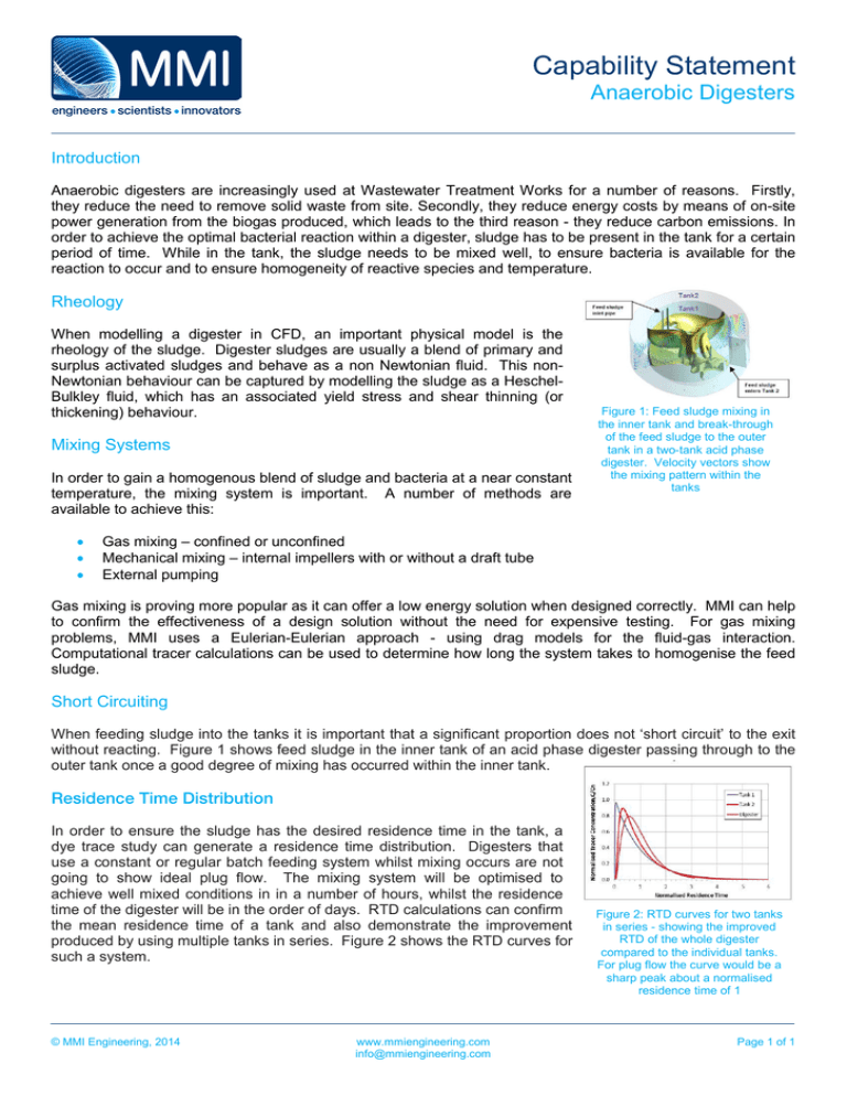
Capability Statement Anaerobic Digesters Introduction Anaerobic digesters are increasingly used at Wastewater Treatment Works for a number of reasons. Firstly, they reduce the need to remove solid waste from site. Secondly, they reduce energy costs by means of on-site power generation from the biogas produced, which leads to the third reason - they reduce carbon emissions. In order to achieve the optimal bacterial reaction within a digester, sludge has to be present in the tank for a certain period of time. While in the tank, the sludge needs to be mixed well, to ensure bacteria is available for the reaction to occur and to ensure homogeneity of reactive species and temperature. Rheology When modelling a digester in CFD, an important physical model is the rheology of the sludge. Digester sludges are usually a blend of primary and surplus activated sludges and behave as a non Newtonian fluid. This nonNewtonian behaviour can be captured by modelling the sludge as a HeschelBulkley fluid, which has an associated yield stress and shear thinning (or thickening) behaviour. Mixing Systems In order to gain a homogenous blend of sludge and bacteria at a near constant temperature, the mixing system is important. A number of methods are available to achieve this: • • • Figure 1: Feed sludge mixing in the inner tank and break-through of the feed sludge to the outer tank in a two-tank acid phase digester. Velocity vectors show the mixing pattern within the tanks Gas mixing – confined or unconfined Mechanical mixing – internal impellers with or without a draft tube External pumping Gas mixing is proving more popular as it can offer a low energy solution when designed correctly. MMI can help to confirm the effectiveness of a design solution without the need for expensive testing. For gas mixing problems, MMI uses a Eulerian-Eulerian approach - using drag models for the fluid-gas interaction. Computational tracer calculations can be used to determine how long the system takes to homogenise the feed sludge. Short Circuiting When feeding sludge into the tanks it is important that a significant proportion does not ‘short circuit’ to the exit without reacting. Figure 1 shows feed sludge in the inner tank of an acid phase digester passing through to the outer tank once a good degree of mixing has occurred within the inner tank. Residence Time Distribution In order to ensure the sludge has the desired residence time in the tank, a dye trace study can generate a residence time distribution. Digesters that use a constant or regular batch feeding system whilst mixing occurs are not going to show ideal plug flow. The mixing system will be optimised to achieve well mixed conditions in in a number of hours, whilst the residence time of the digester will be in the order of days. RTD calculations can confirm the mean residence time of a tank and also demonstrate the improvement produced by using multiple tanks in series. Figure 2 shows the RTD curves for such a system. © MMI Engineering, 2014 www.mmiengineering.com info@mmiengineering.com Figure 2: RTD curves for two tanks in series - showing the improved RTD of the whole digester compared to the individual tanks. For plug flow the curve would be a sharp peak about a normalised residence time of 1 Page 1 of 1
