contemporary/elite low voltage lighting installation
advertisement

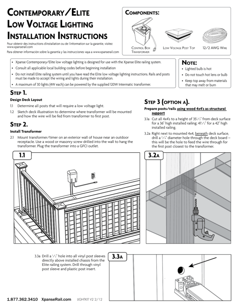
CONTEMPORARY/ELITE LOW VOLTAGE LIGHTING INSTALLATION INSTRUCTIONS COMPONENTS: Pour obtenir des instructions d'installation ou de l'information sur la garantie, visitez www.xpanserail.com Para obtener información sobre la garantía y las instrucciones vaya a www.xpanserail.com CONTROL BOX TRANSFORMER LOW VOLTAGE POST TOP • Xpanse Contemporary/Elite low voltage lighting is designed for use with the Xpanse Elite railing system. • Consult all applicable local building codes before beginning installation 12/2 AWG WIRE NOTE: • Lighted bulb is hot • Do not install Elite railing system until you have read the Elite low voltage lighting instructions. Rails and posts must be made to accept the wiring and lights during their installation. • A maximum of 30 lights (4W each) can be powered by the supplied 120W Intermatic transformer. • Do not touch hot lens or bulb • Keep top away from materials that may melt or burn STEP 1. STEP 3 (OPTION A). Design Deck Layout 1.1 Determine all posts that will require a low voltage light. 1.2 Sketch deck illustration to determine where transformer will be mounted and how the wire will be fed from transformer to first post. STEP 2. Install Transformer 2.1 Mount transformer/timer on an exterior wall of house near an outdoor receptacle. Use a wood or masonry screw drilled into the wall to hang the transformer. Plug the transformer into a GFCI outlet. 1.1 Prepare posts/rails using wood 4x4's as structural support 3.1a Cut all 4x4's to a height of 351⁄2" from deck surface for a 36" high installed railing; 411⁄2" for a 42" high installed railing. 3.2a Right next to mounted 4x4, beneath deck surface, drill a 3⁄4" diameter hole through the deck board – this will be the hole to feed the wire through for the first post closest to the transformer. 3.2A 3.3a Drill a 1⁄2" hole into all vinyl post sleeves directly above installed chassis from the Elite railing system. Drill through vinyl post sleeve and plastic post insert. 1.877.362.3410 XpanseRail.com LIGHTKIT V2 2/12 3.3A 3.4A 3.4a Connect wire to transformer following Intermatic transformer directions. Feed wire from transformer, under deck surface to first post. Feather wire up to the top of the post through the hole previously drilled in the deck board. (Note: make sure the wire is fed through the inside of the vinyl post sleeve covering the 4x4 wood post.) wire 3.5a Feed wire from top of post through the hole in the plastic post insert and vinyl post sleeve. 3.6a Feed the wire through the holes previously drilled in all remaining posts directly along the center of the chassis. (Note: in some cases the holes will be on opposite sides (lines) and in other cases on adjacent sides (corners). Tape wire to chassis to secure the wire in the center of the chassis with packaging tape (not included). Make sure to leave slack in the wire above the wood 4x4's to allow for light connections. 3.6A 3.7a Slide top rail over the assembled chassis, fitting snug to posts. 3.7A 3.8a Through the pre-drilled holes in the top rail baluster spacer and the chassis, screw the provided #10x2" screws through the baluster spacer and chassis into the top rail to connect assembly. 3.8A 1.877.362.3410 XpanseRail.com 3.5A wire STEP 3 (OPTION B). Prepare posts/rails using steel post install kit (73003575) as structural support 3.1b Drill a 1⁄2" hole through "boxing" and deck board (using the bottom base plate as guide) – this will be the hole to feed the wire through for the first post closest to the transformer. 3.1B 3.2b Drill a 1⁄2" hole into all vinyl post sleeves directly above installed chassis from the Elite railing system. Drill through vinyl post sleeve, plastic post insert, and steel post install kit. 3.2B Note: It is recommended to "step" up to the 1⁄2" hole (start with a 1⁄8" hole, then 3⁄8" hole, and finally a 1⁄2" hole to best drill through the steel post.) 3.3b Connect wire to transformer following Intermatic transformer directions. Feed wire from transformer, under deck surface to first post. Feather wire to the top of the post through the hole previously drilled in the deck board. (Note: make sure wire is fed through the inside of the steel post install kit.) 3.3B wire 3.4B 3.4b Feed the wire through the holes previously drilled in all remaining posts directly along the center of the chassis. (Note: in some cases the holes will be on opposite sides (lines) and in other cases on adjacent sides (corners). Tape wire to chassis with packaging tape (not included) to secure the wire in the center of the chassis. Make sure to leave slack in the wire above the post install kit to allow for light connections. 1.877.362.3410 XpanseRail.com 3.5b Slide top rail over the assembled chassis, fitting snug to posts. 3.5B 3.6b Through the pre-drilled holes in the top rail baluster spacer and the chassis, screw the provided #10x2" screws through baluster spacer and chassis into the top rail to connect assembly. 3.6B STEP 4. Connecting low voltage lights to already run wire 4.1 At each post location pull a loop of wire vertically approximately 2". 4.2 Each post light comes standard with a wire extension and connector. Simply lay the wire horizontally in between both connectors and pinch the connectors together until you hear a "snap" causing the sharp copper spikes inside each connector to penetrate the low voltage cable. 4.2 STEP 5. wire extensions from light Connecting lights to posts 5.1 At each post location, on opposite sides, pre-drill through the bottom of flat surface of the top to the post using a 1⁄8" drill bit and connect using supplied screws. OR 5.2 At each post location, use silicone caulk (sold separately) to attach post top to post. 1.877.362.3410 XpanseRail.com 12/2 AWG wire from transformer LIGHTKIT V2 2/12 5.1


