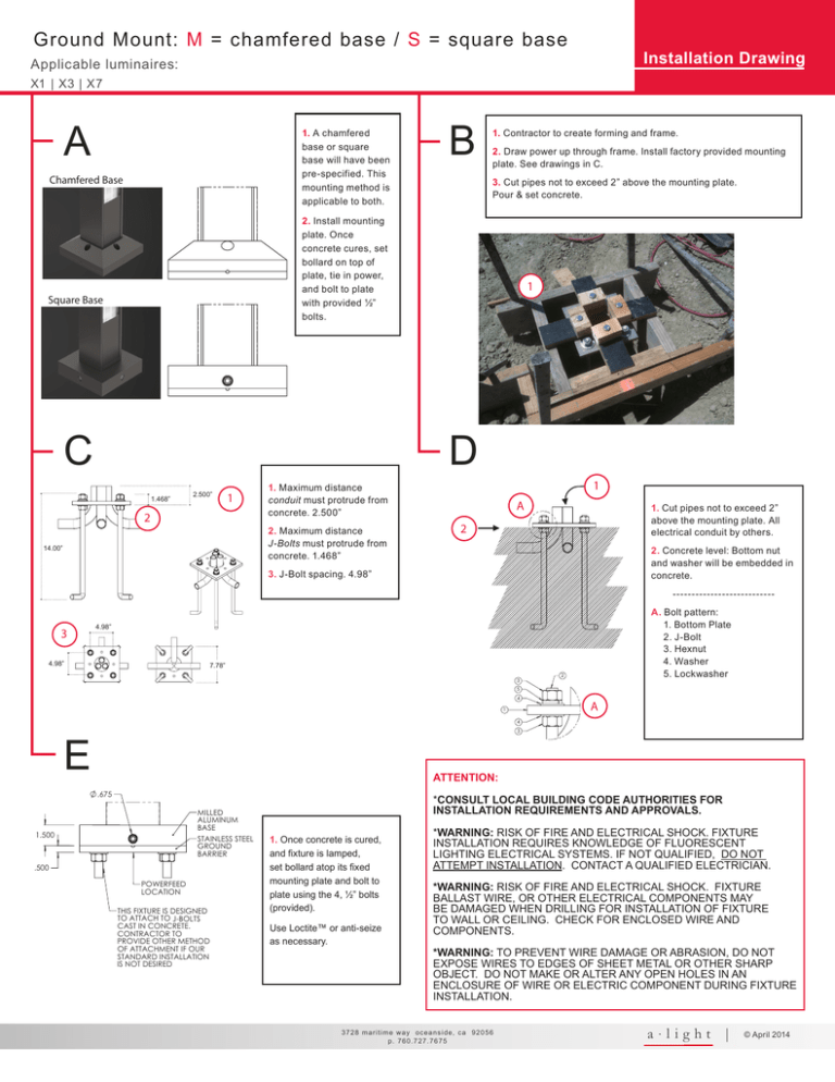
X3 Ground Install
advertisement

Ground Mount: M = chamfered base / S = square base Installation Drawing Applicable luminaires: X1 | X3 | X7 A 1. A chamfered base or square base will have been pre-specified. This mounting method is applicable to both. Chamfered Base B 1. Contractor to create forming and frame. 2. Draw power up through frame. Install factory provided mounting plate. See drawings in C. 3. Cut pipes not to exceed 2” above the mounting plate. Pour & set concrete. 2. Install mounting plate. Once concrete cures, set bollard on top of plate, tie in power, and bolt to plate with provided ½” bolts. Square Base C 1 D 1.468” 2.500” 1 2 2. Maximum distance J-Bolts must protrude from concrete. 1.468” 14.00” 1 1. Maximum distance conduit must protrude from concrete. 2.500” A 1. Cut pipes not to exceed 2” above the mounting plate. All electrical conduit by others. 2 2. Concrete level: Bottom nut and washer will be embedded in concrete. 3. J-Bolt spacing. 4.98” --------------------------- 3 A. Bolt pattern: 1. Bottom Plate 2. J-Bolt 3. Hexnut 4. Washer 5. Lockwasher 4.98” 4.98” 7.78” 3 2 5 4 1 A 4 3 E ATTENTION: .675 MILLED ALUMINUM BASE STAINLESS STEEL GROUND BARRIER 1.500 .500 POWERFEED LOCATION THIS FIXTURE IS DESIGNED TO ATTACH TO J-BOLTS CAST IN CONCRETE. CONTRACTOR TO PROVIDE OTHER METHOD OF ATTACHMENT IF OUR STANDARD INSTALLATION IS NOT DESIRED *CONSULT LOCAL BUILDING CODE AUTHORITIES FOR INSTALLATION REQUIREMENTS AND APPROVALS. 1. Once concrete is cured, and fixture is lamped, set bollard atop its fixed mounting plate and bolt to plate using the 4, ½” bolts (provided). Use Loctite™ or anti-seize as necessary. *WARNING: RISK OF FIRE AND ELECTRICAL SHOCK. FIXTURE INSTALLATION REQUIRES KNOWLEDGE OF FLUORESCENT LIGHTING ELECTRICAL SYSTEMS. IF NOT QUALIFIED, DO NOT ATTEMPT INSTALLATION. CONTACT A QUALIFIED ELECTRICIAN. *WARNING: RISK OF FIRE AND ELECTRICAL SHOCK. FIXTURE BALLAST WIRE, OR OTHER ELECTRICAL COMPONENTS MAY BE DAMAGED WHEN DRILLING FOR INSTALLATION OF FIXTURE TO WALL OR CEILING. CHECK FOR ENCLOSED WIRE AND COMPONENTS. *WARNING: TO PREVENT WIRE DAMAGE OR ABRASION, DO NOT EXPOSE WIRES TO EDGES OF SHEET METAL OR OTHER SHARP OBJECT. DO NOT MAKE OR ALTER ANY OPEN HOLES IN AN ENCLOSURE OF WIRE OR ELECTRIC COMPONENT DURING FIXTURE INSTALLATION. 3728 maritime way oceanside, ca 92056 p. 760.727.7675 a·light | © April 2014 Ground Mount: M = chamfered base / S = square base Installation Drawing Applicable luminaires: X1 | X3 | X7 Notes Applicable Luminaires M or S Ground Mount * Always consult submittal drawings (if applicable) for special circumstances. X1, X3 or X7 endview Fixture Components MAINTENANCE Install lamps prior to mounting: 1. Remove endcaps at top of fixture post & arm end. 1 1. 1/4” thick aluminum extrusion. 9 2. Disconnect wire connector inside at corner endcap. (X3 or X7) post height +18” clearance 3. Disconnect the 8ft lead’s wire connector at base. 2. LED board. 4. Slide out lamp/ballast tray from post and/or arm. 2 3. Internal diffusion lenses. 5. Replace lamps or LED board, reinsert tray. 6. Reconnect corner & base wire connectors. 3 4. Polycarbonate or tempered glass lens. Sealed and gasketed. 7. Reinstall endcaps. 1 4 3.18” aperture 3.9” To maintain: 8. **IMPORTANT** DO NOT CUT 8ft LEAD AT BASE. Coil lead up inside the 2ft unlit section. This long lead allows trays to slide out 8ft without having to disconnect fixture when servicing. Do not kink or bend lead when initially coiling to ease tray sliding for future maintenance. 9. Maintain adequate clearance above bollard for gear tray servicing. 10. Ballast/driver compartment. 10 3/8 X3 shown as example a·light reserves the right to make improvements by changing fixture design or options without notice. w w w. a l i g h t s . c o m


