TruGroove
Installation Instructions
Recessed
ID-39_TruGroove_t-grid
System Overview
Prepare Fixtures/Reference Layout Drawings
These instructions review how to install TruGroove recessed fixtures in T-Grid Ceilings. For
continuous run lengths, please refer to layout drawings supplied by Philips Ledalite in conjunction
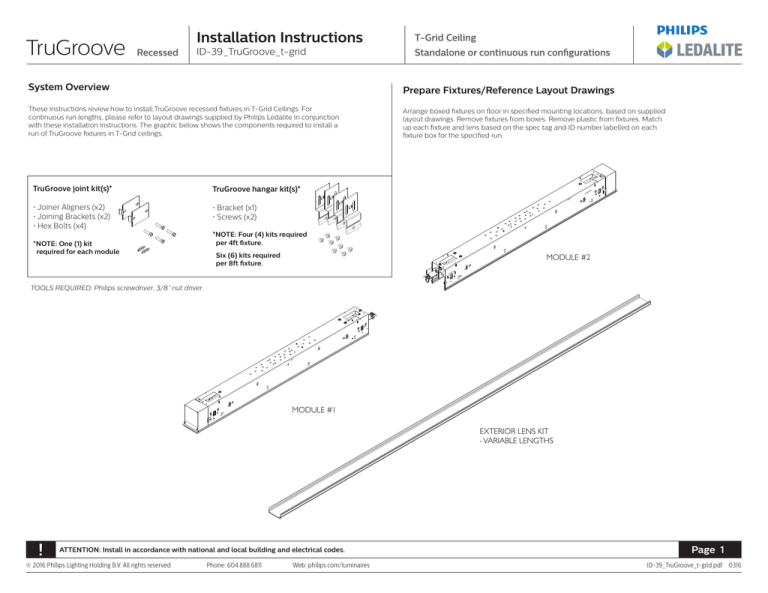
with these installation instructions. The graphic below shows the components required to install a
run of TruGroove fixtures in T-Grid ceilings.
TruGroove joint kit(s)*
TruGroove hangar kit(s)*
• Joiner Aligners (x2)
• Joining Brackets (x2)
• Hex Bolts (x4)
• Bracket (x1)
• Screws (x2)
*NOTE: One (1) kit
required for each module
T-Grid Ceiling
Standalone or continuous run configurations
Arrange boxed fixtures on floor in specified mounting locations, based on supplied
layout drawings. Remove fixtures from boxes. Remove plastic from fixtures. Match
up each fixture and lens based on the spec tag and ID number labelled on each
fixture box for the specified run.
*NOTE: Four (4) kits required
per 4ft fixture.
Six (6) kits required
per 8ft fixture.
MODULE #2
TOOLS REQUIRED: Philips screwdriver, 3/8” nut driver.
MODULE #1
EXTERIOR LENS KIT
- VARIABLE LENGTHS
!
ATTENTION: Install in accordance with national and local building and electrical codes.
© 2016 Philips Lighting Holding B.V. All rights reserved
Phone: 604.888.6811
Web: philips.com/luminaires
Page 1
ID-39_TruGroove_t-grid.pdf 0316
TruGroove
Installation Instructions
Recessed
ID-39_TruGroove_t-grid
T-Bar Ceiling prep
Install Mounting Brackets
T-Grid Ceiling
Standalone or continuous run configurations
Install Fixture Above T-Bar Grid
Install Joiner Aligners
T-Bar Ceiling prep
2
1
9/16˝
9/16˝
9/16˝
9/16˝
Grid 1 3/4˝ Height
Grid 1 11/16˝ Height
Grid 1 31/42˝ Height
Grid 1 11/16˝ Height
9/16˝ Grid 1 1/2˝ Height
9/16˝ Grid 1 1/16˝ Height - 5/16˝ Tegular
9/16˝ Grid 1 1/2˝ Height - 5/16˝ Tegular
915/16
Grid111/1116/˝16˝Height
Height- 5/16˝ Tegular
/16˝˝Grid
915/16
Grid111/12/˝2˝Height
Height- 5/16˝
/16˝˝Grid
15/16˝ Grid 1 11
3/8/16
Height
˝ ˝Height
15/16˝ Grid 1 13/216˝˝Height
Height
15/16˝ Grid 1 3/8˝ Height
15/16˝
3
4
Tegular
Grid 1 3/16˝ Height
4"
4"
Install main T’s, 4” on center.
For continuous row lengths,
refer to supplied layout
drawings. Add 1/4” to the
overall housing length
indicated on your layout
drawings. Position the cross T.
Install T-Grid mounting brackets to required height.
Complete Wiring and
Connect Fixtures
5
6
Install the joiner fixture into the T-Bar Grid
from above. Complete wiring and slide
the fixtures together.
!
Install Mounting Brackets
Install supplied side attachment brackets with
3/8” nut driver.
Phone: 604.888.6811
In the joining fixture install the joiner aligners
in the trim extrusion to approximately halfway.
For standalone unit installation,
skip to step 7.
Note: In the final continuous run module, fully
insert the joiner aligner, tap to beyond 50%.
Secure the Fixture to the Grid
7
ATTENTION: Install in accordance with national and local building and electrical codes.
© 2016 Philips Lighting Holding B.V. All rights reserved
Install the first fixture (or Standalone Unit)
from above the T-Bar Grid.
Web: philips.com/luminaires
Secure the fixture to the T-Bar grid.
Install Power Drop
8
Install power drop at desired location.
For continuous runs, finish installing run first
and then secure to the T-Bar grid.
Page 2
ID-39_TruGroove_t-grid.pdf 0316
TruGroove
Installation Instructions
Recessed
Install Wire Access Covers
9
Install wire access covers to close the fixture.
T-Grid Ceiling
Standalone or continuous run configurations
ID-39_TruGroove_t-grid
Install Seismic Restraints
Install Lamps (Fluorescent
Only)
10
11
Install seismic restraints according to local
building code requirements.
At joint locations, tuck wires inside the housing
and secure the lampholder brackets using
supplied hardware. Ensure brackets sit flush
with the bottom reflectors for a proper lamp fit.
Install Flush Snap In Lens
12
Install lamps if required. LEDs are factory
pre-installed.
Note: lamps are staggered in some
configurations.
Install Regressed Lens
12b
13
13b
Standalone Units: Lenses are supplied in
2’, 4’, or 8’ lengths.
Angle lens to insert into fixture. Lay lens
on aluminum extrusion flange.
OR
Standalone Units: Lenses are supplied in 2, 4,
or 8’ lengths.
Install “snap-in” flush lenses lenses into the
fixture.
Continuous Runs: Lenses are pre-cut to
a maximum of 8’ lengths and are specific
to run lengths. Consult layout drawings for
placement.
!
Continuous Runs: Lenses are pre-cut to
a maximum of 8’ lengths and are specific
to run lengths. Consult layout drawings for
placement.
ATTENTION: Install in accordance with national and local building and electrical codes.
© 2016 Philips Lighting Holding B.V. All rights reserved
Phone: 604.888.6811
Web: philips.com/luminaires
Page 3
ID-39_TruGroove_t-grid.pdf 0316


