Analytic approximations for solar cell open circuit voltage, short
advertisement

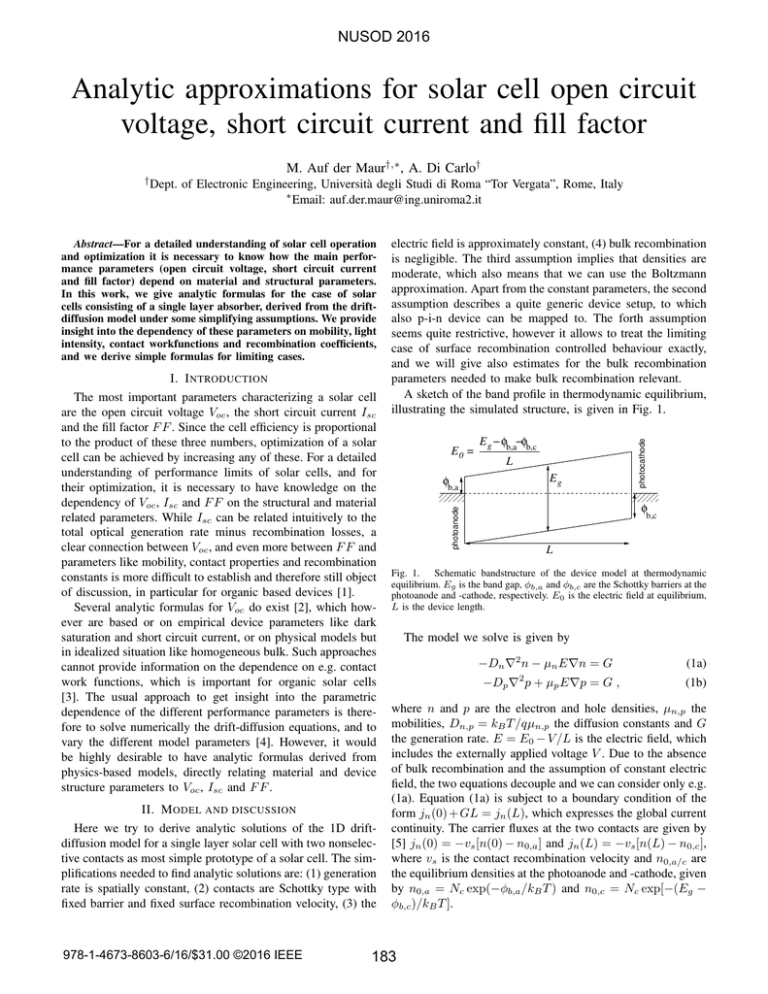
NUSOD 2016 Analytic approximations for solar cell open circuit voltage, short circuit current and fill factor M. Auf der Maur†,∗ , A. Di Carlo† of Electronic Engineering, Università degli Studi di Roma “Tor Vergata”, Rome, Italy ∗ Email: auf.der.maur@ing.uniroma2.it I. I NTRODUCTION The most important parameters characterizing a solar cell are the open circuit voltage Voc , the short circuit current Isc and the fill factor F F . Since the cell efficiency is proportional to the product of these three numbers, optimization of a solar cell can be achieved by increasing any of these. For a detailed understanding of performance limits of solar cells, and for their optimization, it is necessary to have knowledge on the dependency of Voc , Isc and F F on the structural and material related parameters. While Isc can be related intuitively to the total optical generation rate minus recombination losses, a clear connection between Voc , and even more between F F and parameters like mobility, contact properties and recombination constants is more difficult to establish and therefore still object of discussion, in particular for organic based devices [1]. Several analytic formulas for Voc do exist [2], which however are based or on empirical device parameters like dark saturation and short circuit current, or on physical models but in idealized situation like homogeneous bulk. Such approaches cannot provide information on the dependence on e.g. contact work functions, which is important for organic solar cells [3]. The usual approach to get insight into the parametric dependence of the different performance parameters is therefore to solve numerically the drift-diffusion equations, and to vary the different model parameters [4]. However, it would be highly desirable to have analytic formulas derived from physics-based models, directly relating material and device structure parameters to Voc , Isc and F F . II. M ODEL AND DISCUSSION Here we try to derive analytic solutions of the 1D driftdiffusion model for a single layer solar cell with two nonselective contacts as most simple prototype of a solar cell. The simplifications needed to find analytic solutions are: (1) generation rate is spatially constant, (2) contacts are Schottky type with fixed barrier and fixed surface recombination velocity, (3) the 978-1-4673-8603-6/16/$31.00 ©2016 IEEE electric field is approximately constant, (4) bulk recombination is negligible. The third assumption implies that densities are moderate, which also means that we can use the Boltzmann approximation. Apart from the constant parameters, the second assumption describes a quite generic device setup, to which also p-i-n device can be mapped to. The forth assumption seems quite restrictive, however it allows to treat the limiting case of surface recombination controlled behaviour exactly, and we will give also estimates for the bulk recombination parameters needed to make bulk recombination relevant. A sketch of the band profile in thermodynamic equilibrium, illustrating the simulated structure, is given in Fig. 1. E0 = φb,a 111 000 E g − φb,a−φb,c L Eg photocathode Abstract—For a detailed understanding of solar cell operation and optimization it is necessary to know how the main performance parameters (open circuit voltage, short circuit current and fill factor) depend on material and structural parameters. In this work, we give analytic formulas for the case of solar cells consisting of a single layer absorber, derived from the driftdiffusion model under some simplifying assumptions. We provide insight into the dependency of these parameters on mobility, light intensity, contact workfunctions and recombination coefficients, and we derive simple formulas for limiting cases. photoanode † Dept. 111 000 φ b,c L Fig. 1. Schematic bandstructure of the device model at thermodynamic equilibrium. Eg is the band gap, φb,a and φb,c are the Schottky barriers at the photoanode and -cathode, respectively. E0 is the electric field at equilibrium, L is the device length. The model we solve is given by −Dn ∇2 n − µn E∇n = G −Dp ∇2 p + µp E∇p = G , (1a) (1b) where n and p are the electron and hole densities, µn,p the mobilities, Dn,p = kB T /qµn,p the diffusion constants and G the generation rate. E = E0 − V /L is the electric field, which includes the externally applied voltage V . Due to the absence of bulk recombination and the assumption of constant electric field, the two equations decouple and we can consider only e.g. (1a). Equation (1a) is subject to a boundary condition of the form jn (0) + GL = jn (L), which expresses the global current continuity. The carrier fluxes at the two contacts are given by [5] jn (0) = −vs [n(0) − n0,a ] and jn (L) = −vs [n(L) − n0,c ], where vs is the contact recombination velocity and n0,a/c are the equilibrium densities at the photoanode and -cathode, given by n0,a = Nc exp(−φb,a /kB T ) and n0,c = Nc exp[−(Eg − φb,c )/kB T ]. 183 2 An analytic solution of (1a) subject to the aforementioned boundary condition can be found as − kqEL kB T BT − n G − v n e s 0,a 0,c qE Gx − qEx n(x) = n0,a e kB T − + µn E µn E + vs (2) and similar for the holes. From this solution we calculate the current as (assuming electron-hole symmetry) Current density (mA/cm ) NUSOD 2016 I = −q[jn (0) − jp (0)] kB T G 2qvs − qEL − µn E n0,a e kB T − n0,c = qGL − µn E + vs qE (3) While (3) contains all necessary information, it is instructive to look at special cases. In particular, we can distinguish two classes of solutions based on the value of the mobility. The first class corresponds to devices with very low mobilities, as is typically the case in organic materials. In this limit, the current is given by 2kB T 1 I(V ) ≈ qGL 1 − . (4) q Eg − 2φb − V The associated open circuit voltage is found to be 0 0 0.2 0.4 0.6 0.8 1 10 10 9 -1 A (s ) 10 8 An > G 10 7 An < G 10 6 10 -5 (7) Figure 2 shows the current voltage characteristics under illumination for mobilities ranging from 1000 – 10−4 cm2 /Vs, while all other parameters are fixed. It can be seen that high mobility leads to lower Voc but higher F F , while low mobilities reduce F F but provide considerably higher Voc . The higher Voc can be explained by the fact that with low mobility higher carrier densities and gradients are necessary in order to transport the generated carriers towards the contacts where they recombine, driveing the system towards flat band conditions. The higher carrier densities also lead to increased recombination loss at short circuit. For comparison, we give results of numerical drift-diffusion simulations (symbols), showing that only at very low mobility the analytic model starts to deviate systematically from the analytic results, due to charge accumulation near the contacts. We can also notice that crystalline semiconductor solar cells would usually work in the limit of (6), while organic devices would be expected to work in the limit (4). It is of interest to estimate to what extent the assumption of zero bulk recombination is valid. For this we compare the 5 generation rate G with the maximum local recombination rate, which for symmetric parameters is attained at the center of the device (x = L/2). Equating generation and recombination provides an estimate of the recombination parameters necessary to make recombination in the bulk relevant compared to recombination at contacts. For the given parameters device 3 -1 giving for the open circuit voltage n0,c GL kB T ln + . Voc ≈ Eg − 2φb − q n0,a 2vs n0,a 10 Fig. 2. Current voltage characteristics under illumination for different mobilities. The parameters are: Nc = 1019 cm−3 , Eg = 1.42 eV, φb = 0.2 eV, vs = 106 cm/s, qGL = 20 mA, L = 100 nm. The symbols give the results of numerical drift-diffusion simulations. (5) and therefore depends only on the workfunction difference of the two contacts, while the fill factor is approximately F F ≈ √ (1 + γ − 2 γ)/(1 − γ) with γ = (2kB T /q)/(Eg − 2φb ). For the limit of high mobility, on the other hand, the current becomes − qEL I(V ) ≈ qGL − 2qvs n0,a e kB T − n0,c , (6) 2 µn (cm /Vs) 0 1000 0 100 0 10 0 1 0 0.1 0 0.01 0 0.001 0 0.0001 15 Voltage (V) B (cm s ) Voc ≈ Eg − 2φb − 2kB T /q, 20 10-6 10-7 10-8 10-9 10-10 10 -11 10-12 10-13 10 -4 10 2 Bn > G 2 Bn < G -3 10 -2 10 -1 10 0 10 1 10 2 10 3 10 2 mobility (cm /Vs) Fig. 3. Recombination parameters required such that Shockley-Read-Hall or direct/bimolecular bulk recombination becomes dominant. behaviour is mainly controlled by the contact interfaces down to mobilities of around 0.1 – 1 cm2 /Vs. R EFERENCES [1] N. K. Elumalai and A. Uddin, “Open circuit voltage of organic solar cells: an in-depth review,” Energy Environ. Sci., vol. 9, pp. 391–410, 2016. [2] P. Würfel, Physics of Solar Cells. Wiley-VCH Verlag, 2009. [3] A. Zampetti, A. H. Fallahpour, M. Dianetti, L. Salamandra, F. Santoni, A. Gagliardi, M. Auf der Maur, F. Brunetti, A. Reale, T. M. Brown, and A. Di Carlo, “Influence of the interface material layers and semiconductor energetic disorder on the open circuit voltage in polymer solar cells,” Journal of Polymer Science Part B: Polymer Physics, vol. 53, no. 10, pp. 690–699, 2015. [4] W. Tress, K. Leo, and M. Riede, “Optimum mobility, contact properties, and open-circuit voltage of organic solar cells: A drift-diffusion simulation study,” Phys. Rev. B, vol. 85, p. 155201, Apr 2012. [5] S. M. Sze and K. K. Ng, Physics of Semiconductor Devices. John Wiley & Sons, 2006. 184
