4.8. Solar cells
advertisement

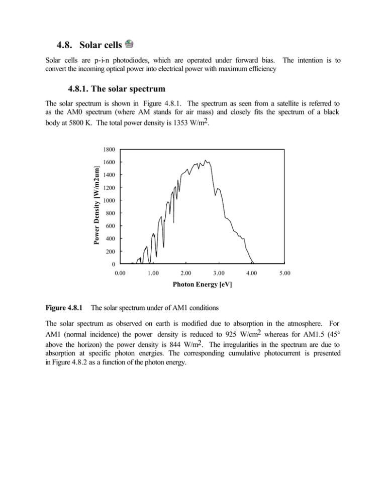
4.8. Solar cells Solar cells are p-i-n photodiodes, which are operated under forward bias. The intention is to convert the incoming optical power into electrical power with maximum efficiency 4.8.1. The solar spectrum The solar spectrum is shown in Figure 4.8.1. The spectrum as seen from a satellite is referred to as the AM0 spectrum (where AM stands for air mass) and closely fits the spectrum of a black body at 5800 K. The total power density is 1353 W/m2. 1800 Power Density [W/m2um] 1600 1400 1200 1000 800 600 400 200 0 0.00 1.00 2.00 3.00 4.00 5.00 Photon Energy [eV] Figure 4.8.1 The solar spectrum under of AM1 conditions The solar spectrum as observed on earth is modified due to absorption in the atmosphere. For AM1 (normal incidence) the power density is reduced to 925 W/cm2 whereas for AM1.5 (45° above the horizon) the power density is 844 W/m2. The irregularities in the spectrum are due to absorption at specific photon energies. The corresponding cumulative photocurrent is presented in Figure 4.8.2 as a function of the photon energy. Cumulative Photocurrent [mA/cm2] 80.00 70.00 60.00 50.00 40.00 30.00 20.00 10.00 0.00 0.00 1.00 2.00 3.00 4.00 5.00 Photon Energy [eV] Figure 4.8.2 Cumulative Photocurrent versus Photon Energy under AM1 conditions 4.8.2. Calculation of maximum power The current through the solar cell can be obtained from: (4.8.1) I = I s (eV a / Vt − 1) − I ph where Is is the saturation current of the diode and Iph is the photo current (which is assumed to be independent of the applied voltage Va ). This expression only includes the ideal diode current of the diode, thereby ignoring recombination in the depletion region. The short circuit current, Isc, is the current at zero voltage which equals Isc = -Iph . The open circuit voltage equals: Voc = Va ( I = 0) = Vt ln( I ph Is + 1) ≅ Vt ln I ph (4.8.2) Is The total power dissipation is then: P = Va I = I s Va (eV a / V t − 1) − I phVa The maximum power occurs at power point are Vm and Im . (4.8.3) dP = 0 . The voltage and current corresponding to the maximal dVa I V dP = 0 = I s ( eV m / V t − 1) − I ph + s m eV m /V t dVa Vt (4.8.4) This equation can be rewritten as: V m = V t ln[ I ph + I s Is V V 1 ] ≅ Vt [ oc − ln( 1 + m )] V Vt Vt 1+ m Vt (4.8.5) by using equation (4.8.2) for the open circuit voltage Voc. A more accurate solution is obtained by solving this transcendental equation and substituting into equations (4.8.1) and (4.8.3). The maximum power can be approximated by: V V Pm = I mVm ≅ −I ph (1 − t )(Voc − Vt ln( 1 + m )) V V (4.8.6) V V V Pm ≅ − I ph (Voc − Vt ln( 1 + m ) − oc t ) Vt Vm (4.8.7) E Pm = −I ph m q (4.8.8) V V V Em = q (Voc − Vt ln( 1 + m ) − oc t ) Vt Vm (4.8.9) m t or where The energy Em is the energy of one photon, which is converted to electrical energy at the maximum power point. The total photo current is calculated as (for a given bandgap Eg ) J ph ( E g ) = q (4.8.10) I ph E m P η= m = Pin qPin (4.8.11) and the efficiency equals: 4.8.3. Conversion efficiency for monochromatic illumination This first order model provides an analytic approximation for the efficiency of a solar cell under monochromatic illumination. We start with the result of section 4.8.2: I ph P V V V η= m = (Voc − Vt ln( 1 + m ) − oc t ) Pin Pin Vt Vm and replace Voc by the largest possible open circuit voltage, Vm = Eg q − Vt ln( 1 + Eg Eg kT q (4.8.12) , yielding: (4.8.13) ) and η= for a GaAs solar cell at 300K, Eg q I phVm Pin = [1 − Eg 2kT ln( 1 + )] Eg kT (4.8.14) = 55 so that the efficiency equals η = 85% 4.8.4. Effect of diffusion and recombination in a solar cell 4.8.4.1.Photo current versus voltage The photo current is obtained by first solving the continuity equation for electrons 0 = Dn d 2n dx 2 + µn E dn n − + g op dx τ (4.8.15) as well as a similar equation for holes. The photo current is obtained from I ph (Va ) = qA d2 d (φ i − Va ) ∫ ( µ n n + µ p p ) dx (4.8.16) 0 Once this photocurrent is obtained the total current is obtained from: I = I s (eV a / Vt − 1) − I ph (Va ) (4.8.17) To obtain the corresponding maximum power one has to repeat the derivation of section 5.3.2. 4.8.5. Spectral response Because of the wavelength dependence of the absorption coefficient one expects the shorter wavelengths to be absorbed closer to the surface while the longer wavelengths are absorbed deep in the bulk. Surface recombination will therefore be more important for short wavelengths while recombination in the quasi-neutral region is more important for long wavelengths. 4.8.6. Influence of the series resistance Vext = Va + IRs (4.8.18) I = I s (eV a / Vt − 1) − I ph (4.8.19) P = Vext I (4.8.20) Repeating the derivation of section 4.8.2 one can show that the maximum power condition is given by the following set of transcendental equations: Vm = Vt ln[ I ph + I s Is 1 V 2I R 1+ m + m s Vt Vt I m = I s ( eV m / V t − 1) − I ph while the maximum external power equals: Pm,ext = Im (Vm + Im Rs) (4.8.21) ] (4.8.22)


