IMPORTANT SAFETY INFORMATION. READ AND FOLLOW ALL SAFETY INSTRUCTIONS. Follow label information
and instructions concerning Wet or Damp Locations, installation near combustible materials, insulation, building materials,
and proper lamping. Do not install in areas subject to combustible vapors or gases. Before wiring to power supply and
during servicing or relamping, turn off power at fuse or circuit breaker. All servicing or relamping must be performed by
qualified service personnel. Product must be grounded to avoid potential electric shock or other potential hazard.
Product must be mounted in locations and at heights and in a manner consistent with its intended use, and in
compliance with the National Electrical Code and local codes. The use of accessory equipment not recommended by
the manufacturer or installed contrary to instructions may cause an unsafe condition. Do not block light emanating from
product in whole or part, as this may cause an unsafe condition. Do not allow items such as drapes, curtains, screens or
the like to come into contact with the product or to block light from the product, as this may cause an unsafe condition.
WARNING – This product contains chemicals known to the State of California to cause cancer, birth defects and/or other
reproductive harm. Thoroughly wash your hands after installing, handling, cleaning, or otherwise touching this product.
MC10LED CYLINDER DMX/RDM
CONNECTION INSTRUCTIONS
CAUTION: DMX inputs and outputs should only be connected to low voltage data connections. Do not
connect any high voltage wiring to the DMX connectors!
NOTE: The DMX wiring and RDM setup should be done by someone experienced in DMX/RDM system installation.
A NOTE ABOUT DMX/RDM SYSTEMS:
DMX512A standards require that DMX devices be installed in a daisy-chain, with no wired “tees”, “wyes” or “star”
connections in the DMX wiring. Installation site conditions may necessitate using a DMX splitter to create a “star”
circuit to distribute the DMX signals. In this case, use a DMX splitter that is compatible with RDM communications
to ensure the fixtures can be addressed correctly after the system is installed. The DMX bus will support up to 32
MC10LED fixtures on one daisy-chain, and the length can be up to 1000 feet (330 meters) long. This maximum is
due to RDM communication timing constraints. No more than four DMX/RDM compatible splitters can be daisy-chained
together per the standard. To maintain DMX data signal integrity, keep data cables away from high voltage power
wiring (especially for long runs), and use shielded twisted-pair cables for problem installations.
The MC10LED Surface/Ceiling Mount (S), Pendant Mount (P), and Wall Mount (W) are shipped with a DMX cable
containing two shielded twisted-pairs (DMX IN and DMX OUT) to allow connection to the DMX/RDM communication
daisy-chain. Only use cables designed for DMX/RDM communication when installing the MC10LED fixtures. DO NOT use
microphone cables to connect DMX/RDM compatible equipment. The electrical properties of microphone cable are not
suitable for reliable DMX/RDM data communication.
The Cord and Cable Mount (CCM) version of the MC10LED cylinder is designed to allow the installer to use standard
CAT5e cables (per ANSI E1.27-2) to interconnect the fixtures and connect to the DMX/RDM control system in a permanent
installation. If the DMX/RDM controller, console, or splitter has different connectors (XLR 3 pin, XLR 5 pin connectors, or
screw terminals) adapters are available to connect the differing connector types.
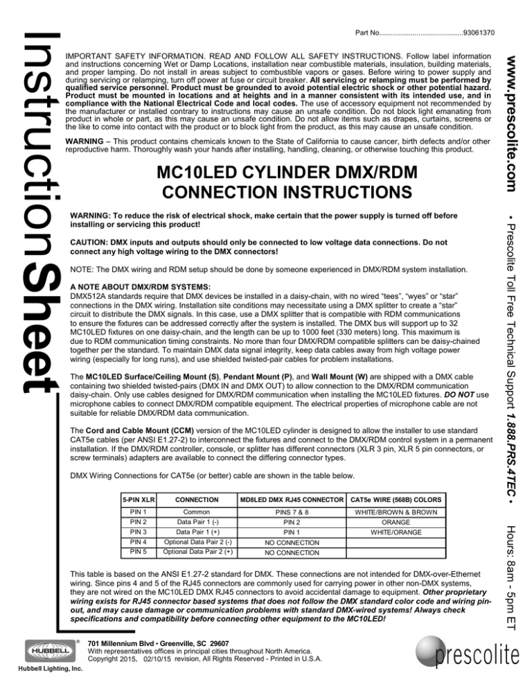
DMX Wiring Connections for CAT5e (or better) cable are shown in the table below.
CONNECTION
MD8LED DMX RJ45 CONNECTOR
CAT5e WIRE (568B) COLORS
PIN 1
Common
PINS 7 & 8
WHITE/BROWN & BROWN
PIN 2
Data Pair 1 (-)
PIN 2
ORANGE
PIN 3
Data Pair 1 (+)
PIN 1
WHITE/ORANGE
PIN 4
PIN 5
Optional Data Pair 2 (-)
Optional Data Pair 2 (+)
NO CONNECTION
NO CONNECTION
This table is based on the ANSI E1.27-2 standard for DMX. These connections are not intended for DMX-over-Ethernet
wiring. Since pins 4 and 5 of the RJ45 connectors are commonly used for carrying power in other non-DMX systems,
they are not wired on the MC10LED DMX RJ45 connectors to avoid accidental damage to equipment. Other proprietary
wiring exists for RJ45 connector based systems that does not follow the DMX standard color code and wiring pinout, and may cause damage or communication problems with standard DMX-wired systems! Always check
specifications and compatibility before connecting other equipment to the MC10LED!
701 Millennium Blvd • Greenville, SC 29607
With representatives offices in principal cities throughout North America.
Copyright 2015, 02/10/15 revision, All Rights Reserved - Printed in U.S.A.
Hours: 8am - 5pm ET
5-PIN XLR
Prescolite Toll Free Technical Support 1.888.PRS.4TEC
WARNING: To reduce the risk of electrical shock, make certain that the power supply is turned off before
installing or servicing this product!
www.prescolite.com
Instruction Sheet
Part No...........................................93061370
Read and follow the provided MC10LED product installation instructions.
Additional DMX wiring instructions are as follows:
MC10LED SURFACE MOUNT (S), PENDANT MOUNT (P)
1.
At the ceiling mount junction box – after installing the power wiring and DMX
control cable in the ceiling mount channel or the pendant mount/stem, make the
power connections in the mounting junction box per the product installation
instructions. Make the DMX control connections (Fig. 1) by connecting the twisted
pair and shield labeled “DMX IN” to the incoming DMX control wiring, and
connecting the twisted pair and shield labeled “DMX OUT” to either the outgoing
DMX wiring to the next fixture in the daisy-chain, or a 120 Ohm terminating resistor
if wiring the last fixture in the daisy-chain. Make sure there are no exposed or
uninsulated wires and connections, and place the wiring and connections in the
mounting junction box. Using an appropriate wiring separator, keep the control
wiring separate from the power wiring in the ceiling mount junction box.
Mount the fixture per the MC10LED product installation instructions, following all
the steps and warnings.
3.
At the fixture wiring compartment – make the power connections in the
MC10LED fixture wiring compartment per the product installation instructions.
Connect the DMX control wiring by connecting the latching 3-pin male connector on
the fixture DMX cable to the female 3-pin connector on the DMX wiring harness
(Fig. 2). The DMX wiring harness has Orange, Orange with White Stripe, and
Brown wires, with the 3-pin connector at one end. Be careful not to pull excessively
on the DMX wiring harness while connecting to it. Rough handling of the harness
may stress or unplug the connections at the LED driver. NOTE: If the fixture has
less than a full complement of drivers (3L, 6L, or 9L versions) there will be DMX
wiring harness driver connectors (8-pin) that are not used/connected at the end of
the harness. They will remain unconnected in the wiring compartment.
4.
Follow the provided MC10LED product installation instructions to complete the
installation.
2.
The DMX control cable and power wiring come preinstalled in the MC10LED wall
mount fixture. Install the fixture and connect the power wiring as instructed by the
MC10LED product installation instructions. Make the DMX control connections
(Fig. 1) by connecting the twisted pair and shield labeled “DMX IN” to the incoming
DMX control wiring, and connecting the twisted pair and shield labeled “DMX OUT”
to either the outgoing DMX wiring to the next fixture in the daisy-chain, or a 120
Ohm terminating resistor if wiring the last fixture in the daisy-chain. Make sure there
are no exposed or uninsulated wires and connections, and place the wiring and
connections in the wall mounting junction box. Using an appropriate wiring
separator, keep the control wiring separate from the power wiring in the wall mount
junction box.
Follow the provided MC10LED product installation instruction to complete the
installation.
MC10LED CORD AND CABLE MOUNT (CCM)
LATCHING
3-PIN MALE
CONNECTOR
Use standard CAT5e cables (by others) to connect the MC10LED to the DMX
control system. There are two RJ45 connectors located on the MC10LED CCM top
casting (Fig. 3). Connect the DMX control “IN” CAT5e cable to the RED “DMX IN”
RJ45 connector, and use the BLUE “DMX THRU” RJ45 connector to connect to the
next fixture in the DMX Daisy-chain using a second CAT5e cable, or if it is the last
fixture in the daisy-chain, plug a 120 Ohm terminator (by others) into the connector.
The CAT5e cables can be tied to the steel cables provided with the MC10LED
CCM fixture using standard nylon wire ties (by others). See the front page of this
document for more details and warnings about using CAT5e cables with DMX
systems.
KEEP THESE INSTALLATION INSTRUCTIONS!
701 Millennium Blvd • Greenville, SC 29607
With representatives offices in principal cities throughout North America.
Copyright 2015, 02/10/15 revision, All Rights Reserved - Printed in U.S.A.
DMX
WIRING
HARNESS
Fig. 2
RJ45
CONNECTORS
DMX IN AND
DMX THRU
Fig. 3
Hours: 8am - 5pm ET
1.
DMX
CONTROL
CABLE
FIXTURE END
3-PIN FEMALE
CONNECTOR
MC10LED WALL MOUNT (W)
1.
Fig. 1
DMX CONTROL
CABLE
JUNCTION
BOX END
Prescolite Toll Free Technical Support 1.888.PRS.4TEC
2.
(+)
UT
XO
DM
(-)
UT
X O IELD
DM
H
TS
OU
(+)
X IN
DM
(-)
D
X IN
IEL
DM
SH
X IN
DM
LABELED DMX
CONNECTIONS
FOR THE
CEILING MOUNT
JUNCTION BOX
www.prescolite.com
Instruction Sheet
Part No...........................................93061370

