FEATURES
GENERAL DESCRIPTION
Pin programmable 1-, 2-, or 3-phase operation
Excellent static and dynamic current sharing
Superior load transient response when used with
ADOPT™ optimal positioning technology
Noise blanking for speed and stability
Synchronous rectification control for optimized light
load efficiency
Soft DAC output voltage transition for VID change
Cycle-by-cycle current limiting
Latched or hiccup current overload protection
Masked power good during output voltage transients
Soft start-up without power-on inrush current surge
2-level overvoltage and reverse voltage protection
The ADP3205A is a 1-, 2-, or 3-phase hysteretic peak current
mode dc-to-dc buck converter controller dedicated to powering
a mobile processor’s core. The chip-optimized low voltage
design runs from the 3.3 V system supply. The chip contains a
precision 6-bit DAC whose nominal output voltage is set by
VID code. The ADP3205A features high speed operation to
allow a minimized inductor size that results in the fastest
possible change of current to the output. To further minimize
the number of output capacitors, the converter features active
voltage positioning enhanced with ADOPT optimal compensation to ensure a superior load transient response. The output
signals interface with ADP3415 MOSFET drivers that are
optimized for high speed and high efficiency. The device is
capable of providing synchronous rectification control to
extend battery lifetime in light load conditions. The ADP3205A
is specified over the extended commercial temperature range of
0°C to 100°C and is available in a 40-lead LFCSP package.
APPLICATIONS
IMVP-IV CPU core dc-to-dc converters
Programmable output power supplies
For more information about the ADP3205A, contact Analog
Devices via email at analog.power@analog.com.
DRV3 DRVLSD3
39
38
DRV2
DRVLSD2
37
DRV1 DRVLSD1
36
35
34
ADP3205A
TSYNC 40
PSI
1
HYSSET
2
VDACREF CURRENTSENSE
HYSTERESIS SET
MUX
AND
VBG
CLIM SET
CLIM/ZCS
CMP
HYS/CLIM
CONTROL
AND
CS MUX/
PHASE CONTROL
33 CS3
32 CS2
31 CS1
30 CS+
29 CS–
CORE
CMP
28 RAMP
27 REG
DRVCTRL
DPSLP
13
VREF
9
DPSHIFT
SET
VREF
BOOT
BOOTSET 10
DPRSET
26 DPSHIFT
REF
MUX
VBG
11
25 DACREF
DPRSLP 12
VID5
3
VID4
4
VID3
5
VID2
6
VID1
7
VID0
8
24 DACREFFB
DAC
RES
NETWORK
VBG
TPWRGD 16
PRWGD
DELAY
DPWRGD 17
PRWGD
MASKING
MASK
PWRGD
LATCH
BOOT
SS 19
SD 18
VCC 22
CORE BELOW CMP
DRVCTRL
COREGD
EOFSS
ALARM
LATCHEN
SS/LATCH-OFF
TIMER
UVLO CMP
BIAS ENABLER
ALARM RST
BAND GAP
AND
REF AMP
VREF
VBG
DVP CMP
23 COREFB
VOV
OVP
LATCH
RVP
LATCH
VRV
RVP CMP
RST
GND 21
20 CLAMP
04847-0-001
VREF
CLKEN 15
ALARM CONTROL
PWRGD 14
DAC REF DIVIDER
CORE ABOVE CMP
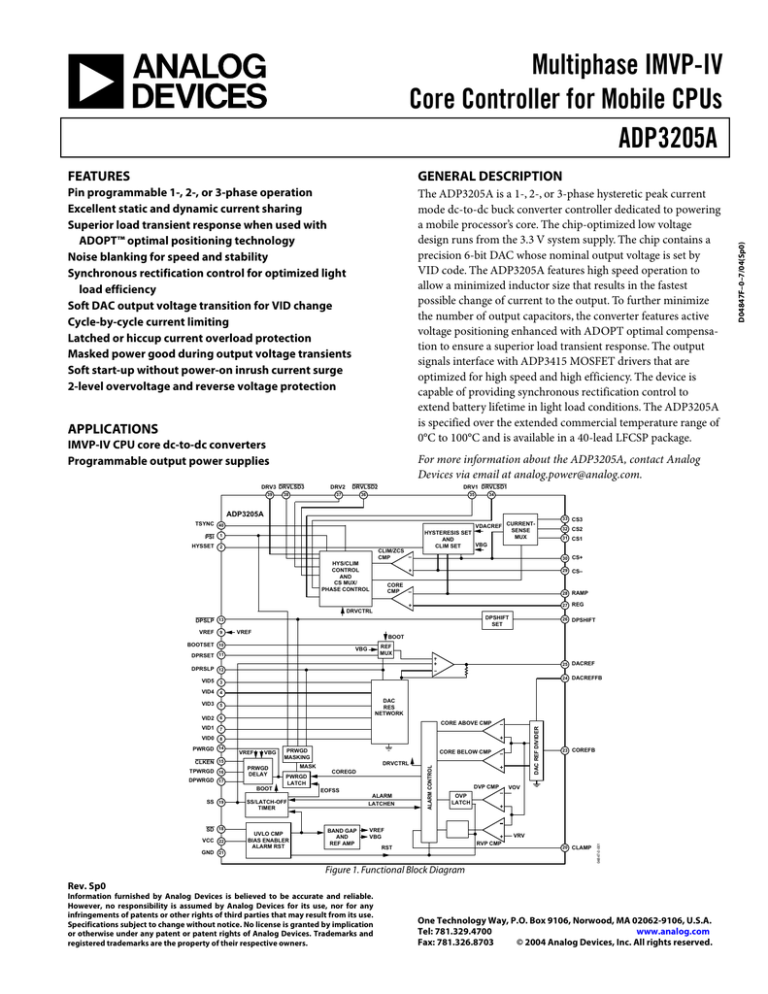
Figure 1. Functional Block Diagram
Rev. Sp0
Information furnished by Analog Devices is believed to be accurate and reliable.
However, no responsibility is assumed by Analog Devices for its use, nor for any
infringements of patents or other rights of third parties that may result from its use.
Specifications subject to change without notice. No license is granted by implication
or otherwise under any patent or patent rights of Analog Devices. Trademarks and
registered trademarks are the property of their respective owners.
One Technology Way, P.O. Box 9106, Norwood, MA 02062-9106, U.S.A.
Tel: 781.329.4700
www.analog.com
Fax: 781.326.8703
© 2004 Analog Devices, Inc. All rights reserved.
D04847F–0–7/04(Sp0)
Multiphase IMVP-IV
Core Controller for Mobile CPUs
ADP3205A


