วิธีการผลิตโอโซนโดยใช เทคนิคพัลส วิดมอดดูเ
advertisement

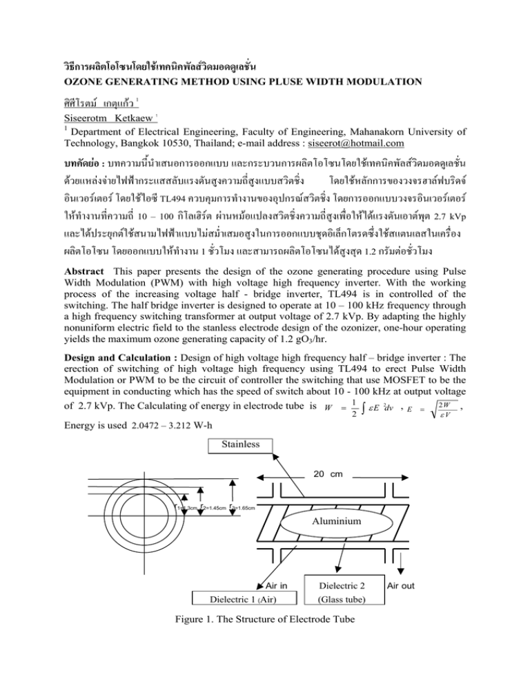
วิธีการผลิตโอโซนโดยใชเทคนิคพัลสวิดมอดดูเลชั่น OZONE GENERATING METHOD USING PLUSE WIDTH MODULATION ศิศีโรตม เกตุแกว 1 Siseerotm Ketkaew 1 1 Department of Electrical Engineering, Faculty of Engineering, Mahanakorn University of Technology, Bangkok 10530, Thailand; e-mail address : siseerot@hotmail.com บทคัดยอ : บทความนี้นําเสนอการออกแบบ และกระบวนการผลิตโอโซนโดยใชเทคนิคพัลสวิดมอดดูเลชั่น ดวยแหลงจายไฟฟากระแสสลับแรงดันสูงความถี่สูงแบบสวิตชิ่ง โดยใชหลักการของวงจรฮาลฟบริดจ อินเวอรเตอร โดยใชไอซี TL494 ควบคุมการทํางานของอุปกรณสวิตชิ่ง โดยการออกแบบวงจรอินเวอรเตอร ใหทํางานที่ความถี่ 10 – 100 กิโลเฮิรต ผานหมอแปลงสวิตชิ่งความถี่สูงเพื่อใหไดแรงดันเอาตพุต 2.7 kVp และไดประยุกตใชสนามไฟฟาแบบไมสม่ําเสมอสูงในการออกแบบชุดอิเล็กโตรดซึ่งใชสแตนเลสในเครื่อง ผลิตโอโซน โดยออกแบบใหทํางาน 1 ชั่วโมง และสามารถผลิตโอโซนไดสูงสุด 1.2 กรัมตอชั่วโมง Abstract This paper presents the design of the ozone generating procedure using Pulse Width Modulation (PWM) with high voltage high frequency inverter. With the working process of the increasing voltage half - bridge inverter, TL494 is in controlled of the switching. The half bridge inverter is designed to operate at 10 – 100 kHz frequency through a high frequency switching transformer at output voltage of 2.7 kVp. By adapting the highly nonuniform electric field to the stanless electrode design of the ozonizer, one-hour operating yields the maximum ozone generating capacity of 1.2 gO3/hr. Design and Calculation : Design of high voltage high frequency half – bridge inverter : The erection of switching of high voltage high frequency using TL494 to erect Pulse Width Modulation or PWM to be the circuit of controller the switching that use MOSFET to be the equipment in conducting which has the speed of switch about 10 - 100 kHz at output voltage of 2.7 kVp. The Calculating of energy in electrode tube is W = 1 ∫ ε E 2dv , E = 2 W , 2 εV Energy is used 2.0472 – 3.212 W-h Stainless 20 cm r1=1.3cm r2=1.45cm r3=1.65cm Aluminium Air in Dielectric 1 (Air) Dielectric 2 (Glass tube) Figure 1. The Structure of Electrode Tube Air out 15 VDC 10k Output 16 15 14 13 12 11 10 9 TL494 1 2 3 4 5 6 7 8 3.6k 0.01 uF 2.2k Figure 2. The Control Circuit (IC TL494) and The Structure of Electrode Tube Results, Discussion and Conclusion: The Testing of High Voltage High Frequency Half bridge Inverter and The Comparison between Frequency and Ozone Quantity. Conclusion : The ozonizer enables to produce the ozone in 1.2 gO3/hr at voltage 2.7 kVp and frequency 100 kHz. In part of switching circuit that controls the voltage of switching transformer , can use the duty cycle (PWM) for adjusting the size of the voltage as needed. Figure 3. (a) Signal of MOSFET drive, (b) Signal of primary voltage of switching transformer and (c) Signal of output voltage of switching transformer at 25 kHz The Comparison between High Frequency and Ozone Quantity High Frequency (kHz) 10 20 30 40 50 60 70 80 90 100 Ozone Quantity (gO3/hr) 0.26 0.35 0.42 0.57 0.66 0.71 0.84 0.89 0.91 1.2 References: [1]. C., G, “High-Frequency Switching Power Supplies-Theory and Design,” New York, McGraw – Hill, 1989. [2]. G. , K.D, “Power Semiconductor Controller drive,” Prentice – Hall, 1989. [3]. R. , M.H , “Power Electronics Circuit Devices and Application,” Prentice – Hall International, 1988. Keyword : ozone, high voltage high frequency transformer and half bridge inverter


