The Fresnel Equations and Brewster`s Law
advertisement
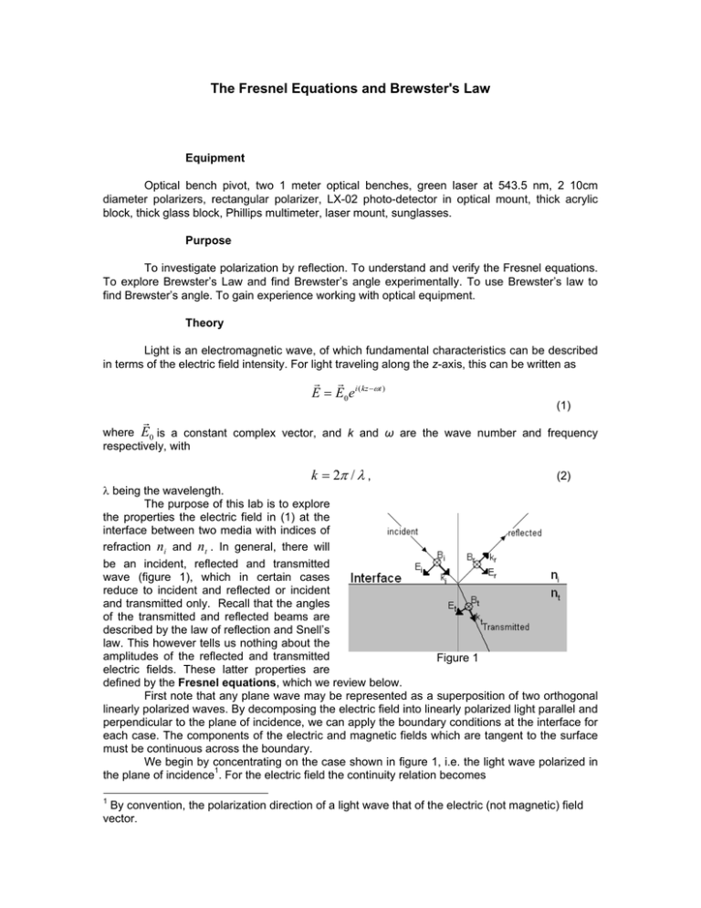
The Fresnel Equations and Brewster's Law Equipment Optical bench pivot, two 1 meter optical benches, green laser at 543.5 nm, 2 10cm diameter polarizers, rectangular polarizer, LX-02 photo-detector in optical mount, thick acrylic block, thick glass block, Phillips multimeter, laser mount, sunglasses. Purpose To investigate polarization by reflection. To understand and verify the Fresnel equations. To explore Brewster’s Law and find Brewster’s angle experimentally. To use Brewster’s law to find Brewster’s angle. To gain experience working with optical equipment. Theory Light is an electromagnetic wave, of which fundamental characteristics can be described in terms of the electric field intensity. For light traveling along the z-axis, this can be written as r r E = E0 e i ( kz −ωt ) (1) r where E0 is a constant complex vector, and k and ω are the wave number and frequency respectively, with k = 2π / λ , (2) λ being the wavelength. The purpose of this lab is to explore the properties the electric field in (1) at the interface between two media with indices of refraction ni and nt . In general, there will be an incident, reflected and transmitted wave (figure 1), which in certain cases reduce to incident and reflected or incident and transmitted only. Recall that the angles of the transmitted and reflected beams are described by the law of reflection and Snell’s law. This however tells us nothing about the amplitudes of the reflected and transmitted Figure 1 electric fields. These latter properties are defined by the Fresnel equations, which we review below. First note that any plane wave may be represented as a superposition of two orthogonal linearly polarized waves. By decomposing the electric field into linearly polarized light parallel and perpendicular to the plane of incidence, we can apply the boundary conditions at the interface for each case. The components of the electric and magnetic fields which are tangent to the surface must be continuous across the boundary. We begin by concentrating on the case shown in figure 1, i.e. the light wave polarized in the plane of incidence1. For the electric field the continuity relation becomes 1 By convention, the polarization direction of a light wave that of the electric (not magnetic) field vector. − Ei cosθ i + Er cosθ i = − Et cosθ t (3) and for the magnetic field Bi + µ1 Br µ1 = Bt (4) µ2 θ r = θ i and we took into account that the r r r r r r vectors E , B , k are mutually orthogonal with E × B oriented along k . Here, µ is the permeability where the law of reflection has been used to set of the material. Further taking into account the fact that in an electromagnetic wave and nα Eα ∝ Bα (with α = i, r , t and nα being the refraction index of the material through which the corresponding wave is propagating) we can write equation (4) as: ni µi ( Ei + Er ) = nt µt Et . (5) Combining with equation (3), we arrive at the Fresnel equations for the wave polarized in the plane of incidence: nt cos θ i − ni cos θ t nt cos θ i + ni cos θ t 2ni cos θi , t|| = nt cosθ i + ni cosθ t r|| = where we’ve supposed that we are in a non-magnetic material ( amplitude reflection/transmission coefficients: Er Ei E t= t Ei r= (6) (7) µ = 1 ) and defined the (8) (9) as the ratios of the amplitude of the reflected electric field to the amplitude of the incident electric field. In the case that the electric field is parallel to the plane of incidence, in much the same way, we derive the second pair of Fresnel equations: ni cos θ i − nt cos θ t ni cos θ i + nt cos θ t 2ni cosθ i t⊥ = ni cos θ i + nt cos θ t r⊥ = (10) (11) Equations (6) and (10) may be conveniently expressed using Snell’s law where they become: sin(θ i − θ t ) sin(θ i + θ t ) tan(θ i − θ t ) r|| = tan(θ i + θ t ) r⊥ = − (12) (13) The reflectance (intensity reflection coefficient) is the square of the amplitude reflection coefficient: R = r2 . (14) The last three equations combine to give: R⊥ = sin 2 (θ i − θ t ) sin 2 (θ i + θ t ) (15) R|| = tan 2 (θ i − θ t ) . tan 2 (θ i + θ t ) (16) Consider now the case in which light is traveling from a medium of lower to higher index of refraction (say, an air/glass interface). Since in this case, θ i > θ t , (15) is never zero. However, the right hand side of equation (16) vanishes when θi + θt = π 2 in which case the denominator becomes infinite. At this point, all incident light which is polarized in the plane tangent to the plane of incidence is transmitted. The value of θ i at which this occurs is known as Brewster’s Angle θB . Writing Snell’s law at Brewster’s angle, ni sin θ B = nt sin θ t = nt sin( π 2 − θ B ) = nt cosθ B , or tan θ B = nt ni (17) which is Brewster’s Law2. 2 Sir David Brewster (1781-1868) is mostly remembered for his invention of the kaleidoscope and for optical improvements of the microscope. However, his main experiments were on the theory of light and its uses. His first paper, "Some Properties of Light", was published in 1813. Brewster's Law was named after him in 1814 when he made measurements on the angle of maximum polarization using biaxial crystals. He was awarded all three of the principal medals of the Royal Society for his optical research. These were the Copley medal in 1815, the Rumford medal in 1818, and the Royal medal in 1830. He was also knighted in 1831. Brewster’s Law may be understood by the following intuitive argument: the electric field vector is transverse to the forward direction. However, at the point where the light polarized in the plane of incidence starts to enter the glass the vibrations in the transmitted wave happen to be parallel to the OR ray in Figure 3. Elementary molecular dipoles inside the material also oscillate along OR, and cannot produce a “reflected” electromagnetic wave propagating in the same direction. This means that only the component polarized normal to the incident plane, SOR, or parallel to the surface, will be reflected. At this point, even if the incident wave has both polarization components (or its polarization its random), ray OR is completely horizontally polarized and the electric field vector is restricted to the plane that is parallel to the reflected surface. This 100% linear polarization can only occur at one angle, because this circumstance is restricted by the fact that the angle between the reflected ray, OR, and the refracted ray, OT, has to be 90o. A graph of the reflectivity (15)-(16) for the air-glass interface as a function of the angle of incidence is shown in Figure 4. At normal incidence, the parallel and perpendicular polarization waves are physically identical, and have the same reflectivity. Notice that even though the glass is transparent, 4% of the light is still reflected. However, as θ i increases, the parallel component drops and the perpendicular component rises, until at the Brewster's angle their values are approximately 0% and 15% of the initial intensity of the light respectively. At an incident angle of 90o, all of the incident light is reflected, so the substance acts as a mirror. The Fresnel equations can be tested by using a pivoting lab bench to vary the incident angle of laser light onto a reflecting surface and measuring the reflected intensity. A photodetector is used in this lab to measure the light intensity. The photodetector is calibrated to generate a voltage proportional to the light intensity, which is then measured with a multimeter. A polarizer between the dielectric surface and the photodetector is used to select the parallel and perpendicular components of the reflected light. Experimental Procedure 1. The theoretical index of refraction for the crown glass and acrylic used in this lab are 1.61 and 1.49 respectively. With these values, use Snell’s Law for θ t , in equations (15) and (16) to make a theoretical plot of the Fresnel Equations similar to figure 4. 2. Throughout this experiment ensure that the apparatus is aligned so that both the reflected and transmitted laser beams are pointed away from the other students, and always keep track of where the beams are. The laser you will be using for this experiment will itself produce polarized light. Place the laser, polarizer, and detector onto the same optical bench. Turn on the laser, voltmeter and the photodetector. Make sure the voltmeter is set to mV setting, and that the detector is set to the 0.1mV = 1Lux setting. 3. The first task is to calibrate the polarizers spatially, and with respect to one another. Since in this experiment, you will need to measure light parallel and perpendicular to the plane of incidence which is determined by your set-up, it is important to know what value on the polarizers correspond to the ⊥ (vertical) and || (horizontal) planes. The rectangular polarizer has its plane of transmission along the longer side. Send the laser through one of the “round” polarizers and the rectangular sheet polarizer oriented vertically. Place a paper card behind both polarizers. Rotate the round polarizer until the transmission through both polarizers is minimized. Make a note of the rotation angle of your polarizer. This angle corresponds to a horizontally polarized wave. Repeat this procedure with the second “round” polarizer. 4. Set up the bench as in figure 4 with the glass slider in the holder. Rotate polarizer 1 to transmit 45° polarization. This will ensure that the light incident onto your glass block has both parallel and perpendicular components. If there is little or no light transmitted through the polarizer at 45°, rotate the laser until a sufficient amount of light is showing. 5. Set Polarizer 2 to transmit horizontally polarized light. Measure the dependence of the reflected intensity on the angle of incidence for this angle varied between 20o to 160o. Take at least 20 data points. Note that the protractor on the pivoting bench reads twice the actual value of θ i as seen in figure 5. Note as well that the height of the beam may change because of the lab desks being uneven. If this occurs, change the height of the detector so that the beam is hitting the center of the face of the photodetector. This is necessary because the photodetector does not have uniform sensitivity across its face. 6. Set Polarizer 2 and the detector on the first optical bench. Measure the intensity transmitted through both polarizers. Use this value to normalize the data obtained in step 5. Plot the normalized data on top of the theoretical curve obtained in step 1. 7. Repeat steps 5 and 6 for the vertically polarized wave. 8. By means of direct observation with a naked eye, find the angle at which the reflection of the parallel polarization wave is minimized. This is your Brewster angle. Determine the index of refraction from equation (17). 9. At the experimental Brewster's angle, take the polarizer off the optical bench. Rotate the sunglasses provided between the block and the detector (as if it were taking the place of the polarizer). Record observations made. 10. Repeat steps 5-7 with the other material (acrylic vs. glass). 11. In step five, the polarizer was placed after the reflecting slide, for analysis. However, the polarizations in question are independent of one another and so the transmission or reflection of a given component does not affect its orthogonal polarization component. Due to this linearity of the optics, a post-selection of the polarization should be equivalent to a pre-selection. Verify this by placing the polarizer before the slide and repeating some of the measurements. 12. After measurements are completed, remember to turn off the photodetector or else the batteries will run out. Error Analysis An interesting systematic error in this lab is the fact that the block reflects more than one dot. As the angle of incidence gets larger, the distance between the dots also gets larger. After a certain angle, three dots can be seen, and then four dots (figure 6). This occurs from the interior reflections that occur inside the block. This becomes a source of systematic error because the secondary reflections are no longer governed by the simple Fresnel formulae (15) and (16). In addition, there is interference between the reflections. To prevent these effects, you should use a sufficiently thick block and ensure that secondary reflections do not hit your detector. Although the general procedure in finding the error in an angle is just half the smallest division, it is different in the case of the angle between the optical benches. The accuracy is reduced because of the way that the apparatus has to be moved. So, it is up to you to decide a suitable error for the angle, within reason. Also, the error in the photodetector is ±5%+0.1mV. However, because the detector is being moved around to accommodate where the laser beam is, the error is higher. Again, you should decide a suitable error for the photodetector. The error in the cos2θ term can be found by standard error propagation from the error in the angle. The uncertainty for measuring the angle of the polarizer and analyzer is half the smallest division on the protractor. To be included with your lab write-up 1. Starting with equation 6, derive equation 12. 2. The theoretical plots made in step 1. 3. A table of values obtained in step 5 for both polarizations and both materials. Show both the raw data and that normalized to the maximum intensity found in step 6. 4. On the theoretical plot of the Fresnel equations plot the data points taken in the experiment with error bars. 5. A value for Brewster’s angle from step 8 with errors. A value for the index of refraction for each plate with error. 6. Discuss the observations made with the sunglasses. Are the sunglasses polarized? What is the purpose of making polarized sunglasses? Explain the significance of which axis the sunglasses are polarized at.
