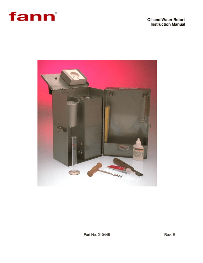
Oil and Water Retort
Instruction Manual
Part No. 210445
Rev. E
Copyright 2009
Fann Instrument Company
Houston, Texas USA
All rights reserved. No part of this work covered by the copyright hereon may be reproduced or copied in any form or by
any means -- graphic, electronic or mechanical without first receiving the written permission of Fann Instrument Company,
Houston, Texas USA
Printed in USA
NOTE:
Fann reserves the right to make improvements in design, construction and appearance of our products without prior notice.
®
FANN is a registered trademark of Fann Instrument Company.
Fann Instrument Company
PO Box 4350
Houston, Texas USA 77210
Telephone: 281- 871-4482
Toll Free: 800-347-0450
Fax: 281- 871-4358
TABLE OF CONTENTS
SECTION
PAGE
1 Description ................................................................................................1
2 Safety Considerations ..............................................................................3
3 Operating Procedure ................................................................................4
4 Care of Equipment....................................................................................5
5 Calculation ................................................................................................6
6 Specifications ............................................................................................7
7 Repair ........................................................................................................9
8 Parts List .................................................................................................13
FIGURES
PAGE
1 Retort Assembly........................................................................................2
2 Retort Kit Assembly ..................................................................................8
3 Retort Wiring, 115 and 230 Volt .............................................................10
4 Retort Wiring 12/115 Volt .......................................................................11
SECTION 1
DESCRIPTION
Oil and Water retorts provide a simple, easy, accurate, and direct reading method of determining the
percentages of water, oil, and solids which make up drilling fluids.
The Oil and Water retort can also be used to determine the amount of water or solids in oil samples, or the
water and oil saturation in core samples.
These retorts are electrically heated and thermostatically controlled to shut off when a predetermined
temperature (930°F ±70°) (498°C ±21°) as specified by API has been reached. Three models are available to
conform to the electric power available. These are: 115 volt, 230 volt, combination 115/12 volt (car battery).
These retorts are available in individual carrying cases or as a part of complete mud testing kits. The retort
module (used in the kits) is also available for use where a carrying case is not necessary.
3
The retort shown in Fig. 1 is composed of a 10 cm drilling fluid chamber (17), measuring lid (18) upper boiling
chamber (19) containing steel wool (22) and distillation tube and condenser (20). The retort, shown in Fig. 2,
is heated by inserting it in a heating well (7) which also contains the cartridge heat (12) and the thermostat (8).
Water and oil distillate are collected in a 10 cc graduate or special collector tube resulting in the percentages
read directly (0.1 cc = 1% readable to 0.5%).
A similar but larger retort is available for use where the additional accuracy of a larger sample is necessary.
3
The model 210465 retort uses a 50 cm sample and a special volumetric flask or special collector tube thus
3
obtaining ± 0.5% accuracy. Special 10 cm collectors are available for more accurate readability.
1
Fig. 1 – RETORT ASSEMBLY
2
SECTION 2
SAFETY CONSIDERATIONS
Safe operation of the Oil and Water Retorts requires that the laboratory technician be familiar with the proper operation
and potential hazards associated with this equipment. Retorting the sample poses the potential hazards of the
exposed retort stem and Condenser getting hot enough to cause burns and serious injury.
Burns can result from touching the hot metal parts of the case near the retort chamber during normal operation. The
operator should be aware of these hot areas and avoid contact with them.
These Retorts are electrically heated, and as with any electrical device if the wiring is allowed to become faulty
electrical shorts can occur causing injury to the operator. These instruments should always be used on a grounded
circuit.
Following is a list of suggestions that should be observed to assure safe operation and maintenance of the Retort Kits.
1. Caution should be exercised by all personnel when an Oil and Water Retort Kit is in operation to avoid injury by
touching the case near the heating jacket or the Retort and condenser assembly while these are hot. Parts of the
case can operate at a temperature where it may cause burns if touched. Safeguard the retort after the test ends
long enough for it to cool. It can still cause burns even after it has been turned off.
2. The practice of removing the retort and condenser and cooling them under water is a very dangerous procedure
and is not recommended because of the danger of severe burns if touched or accidently dropped. Also use
extreme caution when placing a hot retort in water. Hot steam generated when the water hits the hot retort can
cause severe burns.
3. Make sure the electrical source is fused and grounded. Verify the power cord on the Oil and Water Retort Kit is in
good condition and has the proper ground connection.
4. Electrical problems in the wiring or heaters may not be obvious by external observation of the retort. If the retort
repeatedly blows fuses, trips a circuit breaker or heats too slowly or erratically, electrical repairs are indicated.
Refer to Section 7 for repair procedures.
5. Clean the sample chambers (upper and lower) thoroughly after each test, especially the spout. The wire brush,
205850, can be used for spout cleaning. For hard, baked – on materials, a long #31 drill bit, 206118, with handle,
206119, should be used, ensuring that the entrance to the spout inside the sample chamber is clean.
6. After each test, replace the steel wool in the upper chamber to prevent solids buildup.
7. Inspect the threads on the sample chambers (upper and lower) before each test. Check for signs of “belling” of the
threads or for movement (rattling) when the threads are being engaged. These symptoms are signs of abnormal
strain and structural weakening of the threads and could lead to explosive separation under abnormal pressure
conditions.
8. Remove from service each retort, especially for offshore operations, at least once every six months for thorough
examination and cleaning.
3
SECTION 3
OPERATING PROCEDURE
A. Prepare the retort for service by performing steps A through D under Section 4, CARE OF EQUIPMENT.
B. Lift retort assembly, (parts 17, 18, 19, 20), out of heating compartment. (Refer to Fig. 1.) Using the spatula as a
screwdriver, remove the drilling fluid chamber (17) from the retort (19).
C. Pack the upper chamber (19) with steel wool (22). Refer to Fig. 1.
D. Fill drilling fluid chamber (17) with drilling fluid and replace lid (18), allowing excess drilling fluid to escape. Wipe
drilling fluid chamber and outside of lid clean of drilling fluid. (This is a point where error is often introduced. Be
sure that no air is trapped in the chamber. An accurate charge of drilling fluid is very essential.)
E. Clean and lubricate retort threads with high temperature lubricant.
F. Screw drilling fluid chamber (17) with lid (18) into upper chamber (19) and hand tighten.
G. Replace retort assembly in heating compartment and put insulating cover in place.
H. Add a drop of wetting agent to the graduate or collector tube and place under drain port of condenser.
I. Turn heater on by connecting power cord.
NOTE:
The model 210444 combination 115/12 volt retort is provided with three power cords. If the available
power is 115 volts, use the cord with the standard AC plug on one end.
If car battery power or other 12 volt source is to be used, use one of the other two cords. One is adapted to fit a
car cigarette lighter outlet, the other clips directly to the battery. The retort plug and receptacle are polarized so
proper connection is made with any of the three cables.
J. Allow the retort to heat until the pilot lamp (10) goes out. Refer to Fig. 2. This will indicate that the retort has
reached the temperature for distillation to be completed. The thermostat will automatically turn off the power to the
retort heater at the correct temperature regardless of the voltage available. The distillation should be complete in
approximately 20 minutes if rated 115 or 230 voltage is available. A lower voltage may take 25-30 minutes, while
at a higher voltage the distillation may be completed in 15 minutes. Distillation using 12 volt power will take longer,
35 to 45 minutes. After completion of test, disconnect power cord.
K. Read the volume of oil and water. (A drop of wetting agent at this time will often improve the meniscus for easier
reading.)
NOTE:
Nearly 100% recovery of refined oil will be obtained with this retort. If the drilling fluid is made up with
crude oil, calibration runs should be made on a drilling fluid containing a known percentage of the crude
used. Recovery on some crude may be as low as 60%. However, allowing the retort to remain at
maximum temperature for a longer period should improve recovery on paraffin or asphaltic oil. The
correction factor to be used in Section 5, as obtained from this test will be:
FACTOR =
% oil in known sample mud
% oil recovered
4
SECTION 4
CARE OF EQUIPMENT
A. Use the spatula and scrape the dried drilling fluid from the chamber (17) and lid (18) to assure correct drilling fluid
measurement. Refer to Fig. 1.
B. Remove steel wool using the corkscrew, and clean chamber with spatula. Replace any steel wool caked with
drilling fluid with new steel wool (22).
C. Clean the retort drain tube (19) and condenser (20) with a pipe cleaner.
D. Clean and lubricate the retort threads with high temperature lubricant. This is extremely important to prevent
seizing of the threads.
E. The thermostat should allow the retort to reach a dull red heat (approx. 930°F)(498°C) ±70°F (21°C). If adjustment
must be made on thermostat, remove plug (16) in top of heating assembly and turn thermostat shaft clockwise with
screwdriver to lower temperature or counterclockwise to raise temperature. Adjustments are made most easily by
starting below the cutoff point and raising the temperature in small steps (approximately 1/8 turn) until the proper
setting is reached. The retort setting should not be higher than the 970°F (521°C).
5
SECTION 5
CALCULATIONS
Calculate the volume percentages of water, oil and solids as follows:
3
*
A. % Oil by volume = cm oil X 10
3
B. % Water by volume = cm water X 10
3
3
C. % Solids by volume = 100 - (cm oil + cm water) X 10
Calculate weight percentages of the water and oil and the specific gravity of the solids as follows:
3
*
D. Grams Oil = cm oil X 0.84
3
E. Grams water = cm water
F. Grams Drilling Fluid = lb/gal drilling fluid weight X 1.2
G. Grams solids = F - (D + E)
3
3
*
3
H. cm solids = 10 - (cm oil + cm water)
I. Average specific gravity of solids =
J. Solids % by weight =
G
H
G
X 100
F
K. High gravity (4.3) solids % by volume = (1 - 2.5) X 55.6
L. Low gravity (2.6) solids % by volume = 100 - K
* CORRECTION FACTOR =
% oil in known sample
% oil recovered
3
THE CORRECTION FACTOR MAY NEED TO BE APPLIED TO THE CM OIL IN THESE
CALCULATIONS. SEE NOTE IN SECTION 3 FOR EXPLANATION OF CORRECTION FACTOR.
CAUTION
AVERAGE SPECIFIC GRAVITY OF SOLIDS MUST FALL BETWEEN 2.6 AND 4.3. IF IT IS OUT OF THIS
RANGE, AN ERROR HAS BEEN MADE IN TEST OR CALCULATIONS. AN APPROXIMATION OF THE
RELATIVE PROPORTION OF CLAY AND BARITE CAN BE OBTAINED FROM TABLE 1.
TABLE 1
2.6
2.8
3.0
3.2
3.4
3.6
3.8
4.0
4.3
% BY WT.
BARITE
0
18
34
48
60
71
81
89
100
% BY WT.
CLAY
100
82
66
52
40
29
19
11
0
SP.GR
SOLIDS
6
SECTION 6
SPECIFICATIONS
TYPE & SIZE
Part No.
Style
Size in. (cm)
210442
Stainless Steel Case
6-1/4 x 7-1/8 x
10-7/8
(15.9 x 18.1 x 27.6)
10
(4.55)
210443
Stainless Steel Case
6-1/4 x 7-1/8 x
10-7/8
(15.9 x 18.1 x 27.6)
10
(4.55)
210444
Stainless Steel Case
6-1/4 x 7-1/8 x
10-7/8
(15.9 x 18.1 x 27.6)
10
(4.55)
210398
Removable Retort
(From Mud Lab Kits)
(Stainless Steel
Case)
4 x 3-3/4 x 10-7/8
(10.2 x 9.5 x 27.6)
6.5
(2.95)
210465
Stainless Steel Case
9-1/4 x 8 x 10-7/8
(23.5 x 20.3 x 27.6)
25
(11.36)
WT-LB
(kg)
POWER REQUIREMENTS
Part No.
Voltage
Watts
210442
115 V AC/DC
350 @ 115 V
210443
230 V AC
350 @ 230 V
210444
115/12 V AC/DC
350 @ 115 V, 200 @ 12 V
210398
115/12 V AC/DC
350 @ 115 V, 200 @ 12 V
210465
115 V AC
700 @ 115 V
210463
230 V AC
700 @ 230 V
7
Fig. 2 - RETORT KIT ASSEMBLY
8
SECTION 7
RETORT REPAIR
Failure of the retort to properly heat is usually caused by failure of the cartridge heater or the thermostat.
Replacement procedure for either is covered below: Refer to Fig. 2. Figures 3 and 4 illustrate the electrical wiring.
CAUTION: DISCONNECT THE POWER CORD BEFORE BEGINNING REPAIR.
A. Disassembly
1. Remove two screws (15)
2. Remove cover (2) by pulling top outward to clear top of case, then upward.
3.
Carefully remove insulation (6) from around retort adapter. Save if to be re-used.
4. Remove retort adjustment cover(16)
5. Slide out top insulator block (4)
6. Slide out retort assembly consisting of items (3), (7), (8), and (12).
7. Loosen nut then unscrew thermostat mounting screw (14).
8. Remove wires from thermostat switch, (8A) then slide thermostat (8) downward out of retort adapter (7) and
lower insulator (3). The thermostat switch (8A) or the complete thermostat (8) may be replaced at this time.
9. Remove the two retort adapter mounting screws (13) and remove the adapter and heaters from the shelf
insulator block (3).
10. Remove heaters from retort adapter. If these are stuck, drive them out from the top with a suitable punch and
hammer. If heaters are to be replaced the leads must be unsoldered from the power receptacle.
9
RETORT HEATER
205737
TERMOSTAT
SWITCH 205802
RECEPTICAL
205719
CASE GND
RETORT
ADAPTER GND
LAMP HOLDER 205758
BULB 205759
115 VOLTS RETORT WIRING (210442)
TERMOSTAT
SWITCH 205802
RETORT HEATER
205738
RECEPTICAL
205716
CASE GND
RETORT
ADAPTER GND
LAMP HOLDER 205758
BULB 205759
230 VOLTS RETORT WIRING (210443)
Fig. 3 – RETORT WIRING, 115 VOLTS AND 230 VOLTS
10
Fig. 4 - RETORT WIRING, COMBINATION 12/115 VOLT
11
CASE
GND
LAMP HOLDER
205758
BULB 205759
115 V
RECEPTICAL
2057707
TERMOSTAT
SWITCH
205802
LAMP HOLDER
205756
BULB 210397
12V
RETORT
HEATER
205737
115V
RETORT
HEATER
205735
12V
RETORT
HEATER
205735
12V
B. Inspection
While the retort is disassembled it should be checked for cracked or broken insulator blocks, burned or bare wires,
and defective thermostat switch. Replace all burned or damaged parts. Wiring connections are shown in Fig. 3
and 4. Replacement wire must have high temperature insulation such as 205772 18 gauge appliance wire.
C. Re-assembly
Re-assemble in the opposite order of disassembly noting the following:
1. Make sure all wiring connections are proper (good solder connections, tight terminals). Do not use solder
connections near heaters or in any "hot" area.
2. Make sure ground wire is connected to retort adapter mounting screw.
NOTE: Use only rosin core solder.
3. When retort adapter assembly is slid into case make sure no wires are pinched or kinked.
4. Position insulating material (6) on all sides of retort adapter.
5. When re-assembly is complete test retort and adjust thermostat as described in Section 4-E.
D. Pilot Light Replacement
1. Remove lens (9) then bulb (10) by pressing inward and turning.
2. Replace with new bulb and re-assemble lens.
12
SECTION 8
PARTS LIST
Description
Part
No.
205240
Receiver, Retort, 10 cm
205735
3
Description
Part
No.
210450
Adapter, Retort (7A) (7C)
Heater, 100 Watt, 12 Volt, Cartridge (12B)
210451
Insulator Block, Lid (5) for 210442, 210443,
210444
205737
Heater, 350 Watt, 115 Volt, Cartridge
(12A)
210452
Insulator Block, Top (4) for 210442, 210443,
210444
205738
Heater, 350 Watt, 230 Volt Cartridge
(12C)
210445
Instructions, Retort
205755
Switch for Thermostat (8A)
210453
Insulator Block, Shelf (3) for 210442, 210443
205757
Lens, Clear (9)
210455
Insulator Block, Shelf (3)for 210444
205759
Lamp, Neon, NE51, 115 Volt (10A)
210456
Adapter, Retort (7B)
205766
Power Cable, Retort, 230 Volt for 210443
210458
Insulation, Retort, 1 pound (6)
205769
Power Cable, 115 Volt for 210442
210461
Insulator Block, Shelf for 210398
205772
Appliance wire, 18 gauge
210440
Steel Wool, 1/4 pound (22)
205802
Thermostat (8)
210441
Pipe Cleaner
205854
Brush, Test Tube
210439
Corkscrew, Steel Wool Remover
205869
Graduated Cylinder, 10 ml (21)
210437
Condenser (20)
210420
Tube, Centrifuge, 10 ml
210436
Lid, Retort Mud Chamber (18)
209938
Wetting Agent, 1 oz. Dropper Bottle
210435
Thread Lubricant, 1 oz.
210272
Power Cable, 12 Volt Battery Clip
210434
Retort, 10 ml (17) (18) (19)
210273
Power Cable, 115 Volt for 210398
210433
Spatula
210389
Insulator Block, Lid (5) for 210398
210397
Lamp, GE 1816, 12 Volt (10B)
210390
Insulator Block, Top (4) for 210398
210391
Insulator Block, Shelf (3) for 210398
210460
Insulator Block, Top for 210398
13
Warranty
Fann Instrument Company warrants its products to be free from defects in material and workmanship for a period of
12 months from the time of shipment. If repair or adjustment is necessary, and has not been the result of abuse or
misuse within the 12-month period, please return, freight prepaid, and correction of the defect will be made without
charge.
Out of warranty products will be repaired for a nominal charge.
Please refer to the accompanying warranty statement enclosed with the product
Return of Items
For your protection, items being returned must be carefully packed to prevent damage in shipment and insured
against possible damage or loss. Fann will not be responsible for damage resulting from careless or insufficient
packing.
Before returning items for any reason, authorization must be obtained from Fann Instrument Company. When
applying for authorization, please include information regarding the reason the items are to be returned.
Our correspondence address is:
Fann Instrument Company
P.O. Box 4350
Houston, Texas USA 77210
Telephone:
281-871-4482
Toll Free:
800-347-0450
FAX:
281-871-4446
Email:
fannmail@fann.com
Our shipping address is:
Fann Instrument Company
15112 Morales Road, Gate 7
Houston, Texas 77032 USA
14

