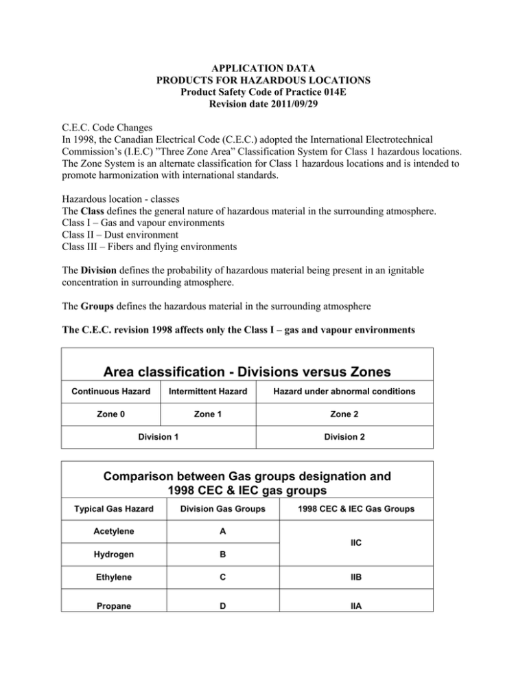
Area classification - Divisions versus Zones
advertisement

APPLICATION DATA PRODUCTS FOR HAZARDOUS LOCATIONS Product Safety Code of Practice 014E Revision date 2011/09/29 C.E.C. Code Changes In 1998, the Canadian Electrical Code (C.E.C.) adopted the International Electrotechnical Commission’s (I.E.C) ”Three Zone Area” Classification System for Class 1 hazardous locations. The Zone System is an alternate classification for Class 1 hazardous locations and is intended to promote harmonization with international standards. Hazardous location - classes The Class defines the general nature of hazardous material in the surrounding atmosphere. Class I – Gas and vapour environments Class II – Dust environment Class III – Fibers and flying environments The Division defines the probability of hazardous material being present in an ignitable concentration in surrounding atmosphere. The Groups defines the hazardous material in the surrounding atmosphere The C.E.C. revision 1998 affects only the Class I – gas and vapour environments Area classification - Divisions versus Zones Continuous Hazard Intermittent Hazard Hazard under abnormal conditions Zone 0 Zone 1 Zone 2 Division 1 Division 2 Comparison between Gas groups designation and 1998 CEC & IEC gas groups Typical Gas Hazard Division Gas Groups 1998 CEC & IEC Gas Groups Acetylene A Hydrogen B Ethylene C IIB Propane D IIA IIC NOTE: the old Division based system is applicable to existing installations and the new Zone system applicable to new installations. It’s obvious that the dual system will coexist for a while and may be referenced in old and new client/consultant specifications. Understanding and indentifying the hazardous environment and material and configure/select the proper product is the most important action to validate and provide the requested records as support. 5.0 APPLICATION LIMITATIONS 5.1 General limitations 5.1.1 These products are designed and approved to handle primarily waste water or similar aqueous solutions in locations classified as hazardous. They are not intended for use in hazardous processes or for deliberately and continuously handling relatively high concentrations of flammable liquids. (i.e. where API approved products are required) 5.1.2 The maximum allowable liquid temperature for Class 1 Zone 1/Division 1or Zone 2/Division 2 is maximum 40º C for submerged products. 5.1.3 Repairs of “Ex” products must be made by ITT W&WW Canada or by a facility approved for hazardous location repairs (i.e. Qualified Facility). 5.1.4 Level sensing in hazardous locations environment: when liquid level sensors ENM-10 or other KPSI are used in Division 1 or 2 hazardous locations, they must be operated at intrinsically safe current levels by provision of intrinsically safe relays in the control panel. At request guidelines can be provided by Technical Department for use of our safe packs kits. 5.1.5 Chemical compatibility: in applications where the pumped or mixed media contain traces of flammable liquids or chemicals, there is a risk of dangerous deterioration of rubber or plastic components such as power cables, cable entry seals, “O”rings and level sensors. The compatibility of these components to the media must be checked by using PSCOP 010 and Crest software. 5.2 Class 1 Division 1 limitations 5.2.1 Division 1 explosion proof approvals are only valid when internal heat sensors installed on these products are connected to a control circuit to initiate motor shut-down. 5.2.2 Division 1 certified products may have only one cable entry, therefore star delta starting is not possible and products must be equipped with one single “composite” (combined power and monitoring) cable of type SOW/SOOW/W/SHD-GC/G-GC. For larger sizes, when composite cables are not available, one single type SOW or W power cable and one type SOW monitoring cable may be used. 5.3 Class 1 Division 2 limitations 5.3.1 The following optional Flygt monitoring devices have been approved as non-incendive by CSA and may be installed inside products approved for Class 1 Div.2 applications: Float leakage sensor (FLS) PN 518 89 01/02 Float switch PN 482 62 00 Temperature sensor PT-100 Stator temperature switched 125ºC, 140ºC, 155ºC


