List of Materials • Breadboard • Connecting Wires • Battery
advertisement

List of Materials
Breadboard
Connecting Wires
Battery
Relay
Voltage Regulator
Capacitor
Ultrasonic Sensor
Arduino Kit
Six-legged Robot Kit
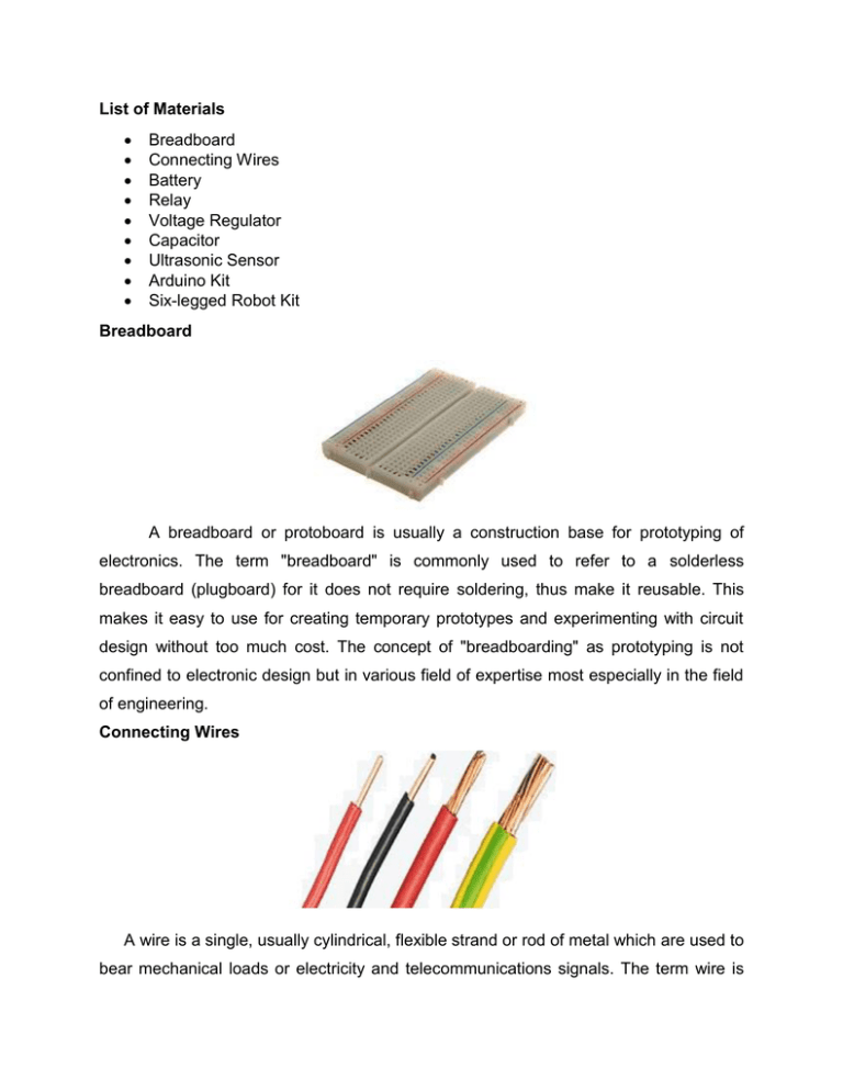
Breadboard
A breadboard or protoboard is usually a construction base for prototyping of
electronics. The term "breadboard" is commonly used to refer to a solderless
breadboard (plugboard) for it does not require soldering, thus make it reusable. This
makes it easy to use for creating temporary prototypes and experimenting with circuit
design without too much cost. The concept of "breadboarding" as prototyping is not
confined to electronic design but in various field of expertise most especially in the field
of engineering.
Connecting Wires
A wire is a single, usually cylindrical, flexible strand or rod of metal which are used to
bear mechanical loads or electricity and telecommunications signals. The term wire is
also used more loosely to refer to a bundle of such strands, as in 'multi-stranded wire',
which is more correctly termed a wire rope in mechanics, or a cable in electricity.
Solid wire, also called solid-core or single-strand wire, consists of one piece of metal
wire, useful for wiring breadboards, cheaper to manufacture than stranded wire and is
used where there is little need for flexibility in the wire. Solid wire also provides mechanical
ruggedness; and, because it has relatively less surface area which is exposed to attack
by corrosives, protection against the environment.
Stranded wire is composed of a number of small gauge wire bundled or wrapped
together to form a larger conductor, more flexible than solid wire of the same total crosssectional area and is used when higher resistance to metal fatigue is required. Stranded
wire tends to be a better conductor than solid wire because the individual wires collectively
comprise a greater surface area.
Battery
An electric battery is a device consisting of one or more electrochemical cells that
convert stored chemical energy into electrical energy. Each cell contains a positive
terminal, or cathode, and a negative terminal, or anode. Electrolytes allow ions to move
between the electrodes and terminals, which allows current to flow out of the battery to
perform work.
Primary batteries are used once and discarded common examples are the alkaline battery
used for flashlights and a multitude of portable devices. While secondary (rechargeable
batteries) can be discharged and recharged multiple times; examples include the leadacid batteries used in vehicles and lithium ion batteries used for portable electronics.
Batteries come in many shapes and sizes, from miniature cells used to power hearing
aids and wristwatches to battery banks the size of rooms that provide standby power
for telephone exchanges and computer data centers.
Reed relay
A relay is an electrically operated switch. Many relays use an electromagnet to operate
a switching mechanism mechanically. Relays are used where it is necessary to control a
circuit by a low-power signal (with complete electrical isolation between control and
controlled circuits), or where several circuits must be controlled by one signal.
A reed relay is a type of relay that uses an electromagnet to control one or more reed
switches. The contacts are of magnetic material and the electromagnet acts directly on
them without requiring an armature to move them. As the moving parts are small and
lightweight, reed relays can switch much faster than relays with armatures. [1] They are
mechanically simple, making for reliability and long life.
Voltage Regulator
A voltage regulator is designed to automatically maintain a constant voltage level. It
may be a simple "feed-forward" design or may include negative feedback control loops.
It may use an electromechanical mechanism, or electronic components. Depending on
the design, it may be used to regulate one or more AC or DC voltages. Electronic voltage
regulators are found in devices such as computer power supplies where they stabilize the
DC voltages used by the processor and other elements.
The common applications of regulators are to step down the output voltage most
especially needed by most semiconductor industry. Most appliances uses regulator to
sustain the stability and performance needed by the integrated circuits (ICs). By all
means, addition of heat sink lessen the heat produce by the voltage regulator that makes
it work for a longer time.
Capacitor
A capacitor (originally known as a condenser) is a passive two-terminal electrical
component used to store energy electrostatically in an electric field. The forms of practical
capacitors vary widely, but all contain at least two electrical conductors (plates) separated
by a dielectric (insulator). The conductors can be thin films of metal, aluminum foil or
disks, etc. The "non-conducting" dielectric acts to increase the capacitor's charge
capacity. A dielectric can be glass, ceramic, plastic film, air, paper, mica, etc. Capacitors
are widely used as parts of electrical circuits in many common electrical devices. Unlike
a resistor, an ideal capacitor does not dissipate energy instead stores energy in the form
of an electrostatic field between its plates.
Ultrasonic Sensor
“Ultrasonic” refers to very high-frequency sound – sound that is higher than the range
of human hearing. Sound Navigation And Ranging (Sonar) is an application of ultrasonic
sound that uses propagation of these high frequency sound waves to navigate and detect
obstacles. Ultrasonic sensors (also known as transceivers when they both send and
receive, but more generally called (transducers) work on a principle similar
to radar or sonar, which evaluate attributes of a target by interpreting the echoes from
radio or sound waves respectively. The ultrasonic sensor determines the distance to a
reflective surface by emitting high-frequency sound waves and measuring the time it
takes for the echo to be picked up by the detector.
Active ultrasonic sensors generate high frequency sound waves and evaluate the
echo which is received back by the sensor, measuring the time interval between sending
the signal and receiving the echo to determine the distance to an object. Passive
ultrasonic sensors are basically microphones that detect ultrasonic noise that is present
under certain conditions.
Arduino Nano
The Arduino Nano is a small, complete, and breadboard-friendly board based on the
ATmega328 (Arduino Nano 3.0) or ATmega168 (Arduino Nano 2.x). It has more or less
the same functionality of the Arduino Duemilanove, but in a different package. It lacks
only a DC power jack, and works with a Mini-B USB cable instead of a standard one. The
Nano was designed and is being produced by Gravitech. It includes TX/RX, power and
test LED’s, reset button, analog and digital pins, ICPS Header and voltage regulator.
Six-legged Robot
It is commonly called as hexapod robot which is a mechanical vehicle that walks on
six legs. Since a robot can be statically stable on three or more legs, a hexapod robot has
a great deal of flexibility in how it can move. Its feet are typically pointed, but can also be
tipped with adhesive material to help climb walls or wheels so the robot can drive quickly
when the ground is flat.
Procedure
1. Place the Arduino Nano on your breadboard where it most suited.
2. Connect the positive supply of the battery (6 V) to the input of the voltage
regulator (LM7805) together with a 1 µf capacitor while the negative supply to the
ground together with a 22 µf capacitor. (Note. Use a common ground to the
whole circuit.)
3. Connect the output of the voltage regulator to the Vcc of the Arduino Nano.
4. Ultrasonic sensor (HC-SR04) trigger pin is connected to the input pin number 2
of the Arduino Nano, echo pin to the input pin number 4 and supply to the Vcc.
5. Connect pin number 2 of Relay 1 to input pin number 7 of the Arduino which
responsible to the six-legged robot forward motion and Vcc for the supply.
6. Connect pin number 2 of Relay 2 to input pin number 9 of the Arduino which
responsible to the six-legged robot right motion and Vcc for the supply.
If all steps are done the circuits must look like this. Program is made at Arduino
software language.
Schematic Diagram
Program
const int trigPin = 2;
const int echoPin = 4;
int turnright = 9;
int forward = 7;
void setup()
{
Serial.begin(9600);
pinMode(turnright,OUTPUT);
pinMode(forward,OUTPUT);
}
void loop()
{ pinMode(trigPin, OUTPUT);
digitalWrite(trigPin, LOW);
delayMicroseconds(2);
digitalWrite(trigPin, HIGH);
delayMicroseconds(10);
digitalWrite(trigPin, LOW);
pinMode(echoPin, INPUT);
duration = pulseIn(echoPin, HIGH);
inches = microsecondsToInches(duration);
cm = microsecondsToCentimeters(duration);
//Serial.print(inches);
//Serial.print("in, ");
//Serial.print(cm);
//Serial.print("cm");
//Serial.println();
//delay(100);
if(cm>=0&&cm<=50)
{digitalWrite(forward,LOW);
digitalWrite(turnright,HIGH);
delay(300);digitalWrite(turnright,LOW);}
else
{digitalWrite(forward,HIGH);}
}
long microsecondsToInches(long microseconds)
{
return microseconds / 74 / 2;}
long microsecondsToCentimeters(long microseconds)
{return microseconds / 29 / 2;}

