P9 Data Contact Blocks
advertisement

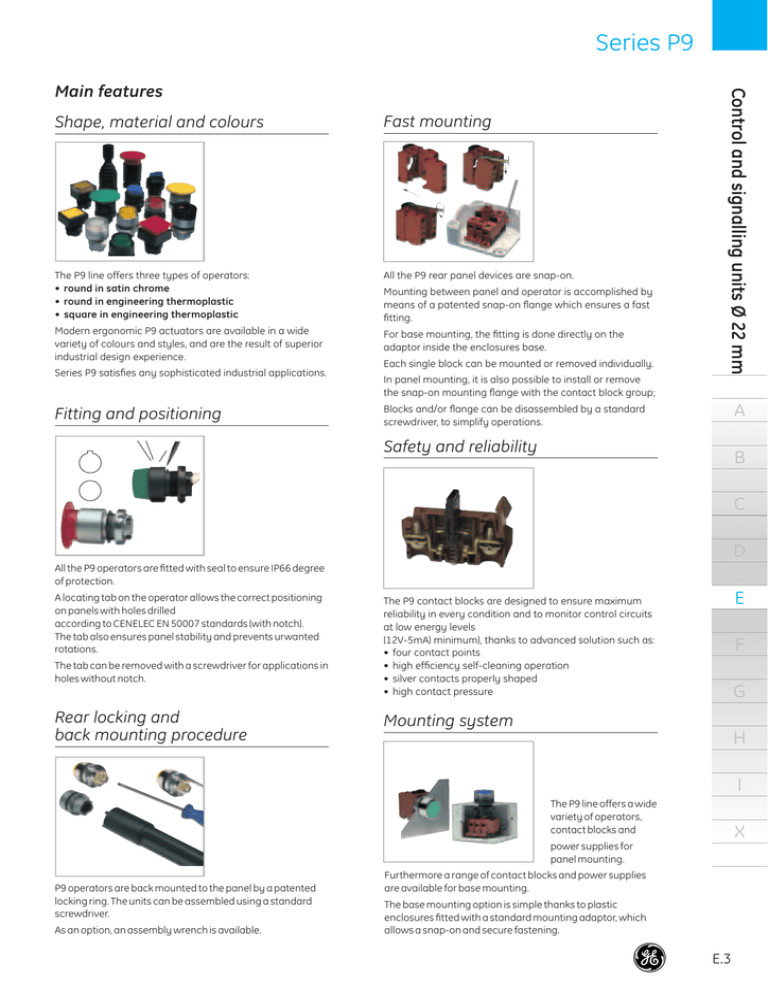
Series P9 Shape, material and colours Fast mounting The P9 line offers three types of operators: • round in satin chrome • round in engineering thermoplastic • square in engineering thermoplastic All the P9 rear panel devices are snap-on. Modern ergonomic P9 actuators are available in a wide variety of colours and styles, and are the result of superior industrial design experience. For base mounting, the fitting is done directly on the adaptor inside the enclosures base. Series P9 satisfies any sophisticated industrial applications. Fitting and positioning Mounting between panel and operator is accomplished by means of a patented snap-on flange which ensures a fast fitting. Each single block can be mounted or removed individually. Control and signalling units Ø 22 mm Main features In panel mounting, it is also possible to install or remove the snap-on mounting flange with the contact block group; A Blocks and/or flange can be disassembled by a standard screwdriver, to simplify operations. Safety and reliability B C D All the P9 operators are fitted with seal to ensure IP66 degree of protection. A locating tab on the operator allows the correct positioning on panels with holes drilled according to CENELEC EN 50007 standards (with notch). The tab also ensures panel stability and prevents urwanted rotations. The tab can be removed with a screwdriver for applications in holes without notch. Rear locking and back mounting procedure E The P9 contact blocks are designed to ensure maximum reliability in every condition and to monitor control circuits at low energy levels (12V-5mA) minimum), thanks to advanced solution such as: • four contact points • high efficiency self-cleaning operation • silver contacts properly shaped • high contact pressure F G Mounting system H I The P9 line offers a wide variety of operators, contact blocks and X power supplies for panel mounting. P9 operators are back mounted to the panel by a patented locking ring. The units can be assembled using a standard screwdriver. As an option, an assembly wrench is available. Furthermore a range of contact blocks and power supplies are available for base mounting. The base mounting option is simple thanks to plastic enclosures fitted with a standard mounting adaptor, which allows a snap-on and secure fastening. E.3 Control and signalling units Ø 22 mm Series P9 A Technical data Compliance with standards Metal operators Plastic operators IEC 947.5.1 - VDE 0660 - NFC 63140 IEC/EN 60947.5.1 - UTE - BSI - NEMA CENELEC EN 50007 With fuses 16A gG according to IEC 269.1 and 269.3. cUL U.S. - RINA - CE - GOST R - Lloyd’s Register of Shipping - Bureau Veritas - Germanischer Lloyd Climatic protections The standard versions are suitable for use in the following climates: Temperate climate cat. 23/50 (DIN 50014) Wet climate cat. 23/83 (DIN 50015) Hot wet climate cat. 40/92 (DIN 50015) Variable wet climate FW24 (DIN 50016) Temperature ranges D Performances of the contacts • • • • • • Slow acting Self-cleaning sliding NC forced breaking Double movable bridge Four switching points Double break Electrical resistance of the contact Operation -25 °C to + 70 °C Storage -40 °C to + 70 °C IP66 according to CENELEC EN 60529 when they are mounted into enclosures with the same or a higher degree of protection. Suitable for using into enclosures type NEMA 1-3-3R-3S-4-4X-12-13 according to UL 508. C Class I Class II (double insulation) Short-circuit protection Approvals Protection degree of the operators B Electrical shocks protection (acc. IEC 536) < 25 m V according to IEC 255, cat. 3 Identification of the terminals According CENELEC EN 50013 Electrical performances Rated thermal current Ith = 10 A Performances according IEC 947.5.1 Protection degree of the terminals Categorie AC 15 Voltage Ue (V) 24 48 60 IP2x according to CENELEC EN 60529. Current Ie (A) 10 10 10 Voltage Ue (V) 24 48 60 110 220 300 Current Ie (A) 2.5 1.4 1 0.55 0.27 0.2 110 220 380 500 600 6 3 2 Categorie DC 13 Shock resistance (acc. to MIL 202 B method 202 A) 1/2 sinusoid 11 ms: No damage or disassembling at 100 g for all devices, except for the illuminated operators with transformer 38 g. E F Performances according to CSA and UL AC Heavy Duty (A600) DC Standard Duty (Q300) Vibration resistance (according to IEC 68-2-6) 16 g with frequency range from 40 to 500 Hz and maximum shifting 0.75 mm (peak-to-peak). G Rated insulation voltage H 690V according to EN 60947.1 Impulse withstand voltage I 4 kV according to EN 60947.1 Insulation class X Groep C according VDE 0110 E.6 Operating range V 12 5 mA 1.5 1.2 Series P9 Number of electrical contacts Electrical endurance Flange standard optional 3 positions 5 positions Alternative current 50/60 Hz cat. AC 15 Million of operations 600V 220V 110V48/24V 1 0.5 0.1 0.05 0.01 0.1 0.5 5 1 10 Current (A) Direct current cat. DC 13 48V max 8 max 4 - max 4 max 2 - max 4 max 4 max 2 max 2 Fitted for panels 1 to 6 mm. thick with holes drilled according to CENELEC EN 50007 standards. 24V 1 0.5 3.2 .125" 0.1 50mm 1.97" 0.05 0.01 0.1 max 4 A 22.5 .88" B 23.5 .93" Million of operations 110V max 8 Mounting Ith 220V max 6 Technical data Standard push-buttons Mushroom head push-buttons Emergency lever Standard selectors Key selector switches Joysticks Key push-buttons Selector push-buttons Toggle switches Mushroom head with lock Mushroom head push-buttons 3 pos. Illuminated push-buttons Illuminated mushroom head push-buttons Illuminated selector switches Illuminated mush. push-buttons with lock Illuminated mush. push-buttons 3 pos. Ith 0.5 1 5 30mm 1.18" flange with 3 positions 10 C Current (A) 50mm 1.97" flange with 5 positions Mechanical endurance Locking emergency Mushroom head push-buttons 3 positions Illuminated mushroom head push-buttons 3 pos. Joysticks Key push-buttons Toggle switches Illuminated selector switches Push-on push-off device Standard selector switches Key selector switches Illuminated push-buttons Selector push-buttons Emergency lever Standard push-buttons Mushroom head push-buttons D 0.3 Mil./op. E 0.5 Mil./op. F 1 Mil./op G 3 Mil./op. H Rear panel modularity The P9 series is composed with 10 mm or a multiple of 10 mm modular units, fitted side by side on a proper mounting flange. The standard operators are supplied with a three position flange with a capacity of 3 units of 10 mm or 1 of 10 mm and 1 of 20 mm or 1 of 30 mm. When the three position flange is not enough to satisfy the applications needs, the five position flange is required to add two more units of 10 mm mounted side by side. Using the five position flange take into account the bigger with (50 mm instead of 30 mm). I X E.7 Control and signalling units Ø 22 mm Series P9 Contact blocks Cat. no. Ref. no. P9B01FH P9B10FH 187014 187015 P9ACFSM 187846 P9PDHF 187056 Cat. no. Ref. no. NC+NO P9B11VN 187000 NC+NC P9B02VN 187008 NO+NO P9B20VN 187009 NC P9B01VN 187001 NO P9B10VN 187002 NC late opening P9B01VR 187003 F NO early closing P9B10VA 187004 G NC+NO delayed P9B11T3 P9B11T8 187010 187011 Logic Reed A new range of LOGIC REED contact blocks with faston terminals for use with power lower than 12V - 5mA. Contact type Rated voltage Rated current Rated power Minimum centerline distance Mounting on operators NC NO AC2 to 120V max. DC2 to 30V max. AC/DC - 0.001 to 0.15A max. AC - 8VA max. DC - 4.5W max. 30x32 mm. through specific bayonet flange adaptor. Full voltage power supply Contact type With screw min. 1 of 22 AWG (0.32 mm2) max. 2 of 12 AWG (3.3 mm2) A ---- B ---- C D E H I 0.1-30 sec 10-180 sec Faston NC P9B01FN 187012 1 x (6.35 x 0.8 mm) 2 x (2.8 x 0.8 mm) NO P9B10FN 187013 Terminal adapter NO P9ACA6 188804 X printed circuit board adapter The catalogue numbers in bold are available from stock. E.20 Series P9 Power supplies Position on flange 2 3 1 With screw Contact type Cat. no. Ref. no. P9PDNV0 187020 Logic Reed fullvoltage for low power P9PDHF 187056 Long life 110/120V O BA9S 130V-2W included P9PRLVJ 187021 Resistor + Diode 220/240 V ^ BA9S 130V-2W included P9PRDVN 187022 Resistor 110/120V O BA9S 60V-1.2W included P9PRNVJ 187023 220/240V O BA9S 130V-2W included P9PRNVN 187024 Resistor ENEL version BA9S 48V-2W included 110V O P9PREVJ 187025 125/127V O P9PREVL 187026 P9PDTV0 187027 ■ UL-CSA: BA9S max 250V-2W not included Test full voltage (1) O IEC: BA9S max 380V-2W not included P9PRTVN 187028 ■ Test resistor (1) 220/240 V O BA9S 130V-2W included min. 1 of 22 AWG (0.32 mm2) max. 2 of 12 AWG (3.3 mm2) ■■■ Full voltage O IEC: BA9S max 380V-2W not included UL-CSA: BA9S max 250V-2W not included ■■■ ■ ■ Transformer 50/60 Hz BA9S 6V-1.5W included ■ Faston ■■■ A C P9PDMVD 187040 Multifunction (2) full voltage 110V O BA9S 130V-2W included P9PDMVJ 187041 Full voltage IEC:BA9S max 380V-2W not included UL-CSA: BA9S max 250V-2W not included : P9PTMV see bottom P9PDNF0 187055 D E F G 1 x (6.35 x 0.8 mm) 2 x (2.8 x 0.8 mm) Integrated LED Standard light x1 ■■■ 24V AC/DC 120V AC 230V AC P9PLNVD• P9PLNVJ• P9PLNVN• see bottom see bottom see bottom 24V AC/DC 120V AC 230V AC P9PLFVD• P9PLFVJ• P9PLFVJ• see bottom see bottom see bottom Flashing light x2 H I X (1) LED colour• (2) B see bottom P9PTNV Multifunction (2) full voltage 24V O BA9S 24V-2W included Multifunction (2) Transformer 50/60 Hz BA9S 6V-0.6W included Panel mounting ■■■ Do not connect for flashing light Link to external contact in order to have steady or flashing light C closed = Steady light C open = Flashing light orange white yellow blue red green A B G L R V The catalogue numbers in bold are available from stock. Voltage : 110- 220-250 380 415-440 480-500 Y W U N J U N J For reference numbers, see chapter X, pg. X.10 E.21 Series P9 Contact blocks Contact type With screw min. 1 of 22 AWG (0.32 mm2) max. 2 of 12 AWG (3.3 mm2) Ref. no. NC P9B01BN 187017 NO P9B10BN 187018 Cat. no. Ref. no. P9PDNB0 187070 Power supplies Position on flange 2 3 1 With screw Bulb power supply min. 1 of 22 AWG (0.32 mm2) max. 2 of 12 AWG (3.3 mm2) ■■■ Full voltage O IEC: BA9S max 380V-2W not included UL-CSA: BA9S max 250V-2W not included Base mounting Cat. no. A Integrated LED Standard light x1 24V AC/DC 120V AC 230V AC ■■■ P9PLNBD• P9PLNBJ• P9PLNBN• see bottom see bottom see bottom B x2 C The catalogue numbers in bold are available from stock. orange white yellow LED colour• A B G blue red green L R V D E F G H I X For reference numbers, see chapter X, pg. X.10 E.23 Series P9 Contact blocks P9B01FN / P9B011VN / P9B02VN / P9B20VN P9B11T– Panel mounting P9B01V– / A Power supplies P9PDNV0 / P9PRLV– / P9PRDV– P9PDNF0 B C D E P9PRNV– / P9PDTV0 / P9PRTV– P9PREV– F G H P9PTNV– P9PDMV– / I X E.39 Control and signalling units Ø 22 mm Series P9 Dimensional drawings Push-on / push-off devices Protection cover P9ACRCL P9ACDPP Insert holders and plates P9ARTBM P9ARTWM P9ARTTM P9ARTBS P9ARTWS P9ARTTS P9ASTBS P9ASTWS P9ASTTS A B C 080XTGR– – 080XTG8– – D E F G Contact blocks P9PDNBO P9B01BN P9B10BN H I X E.40 Power supplies (1) With insert holder (2) Without insert holder


