PIR MOTION DETECTION MODULE Description The Passive
advertisement

PIR MOTION DETECTION MODULE
Description
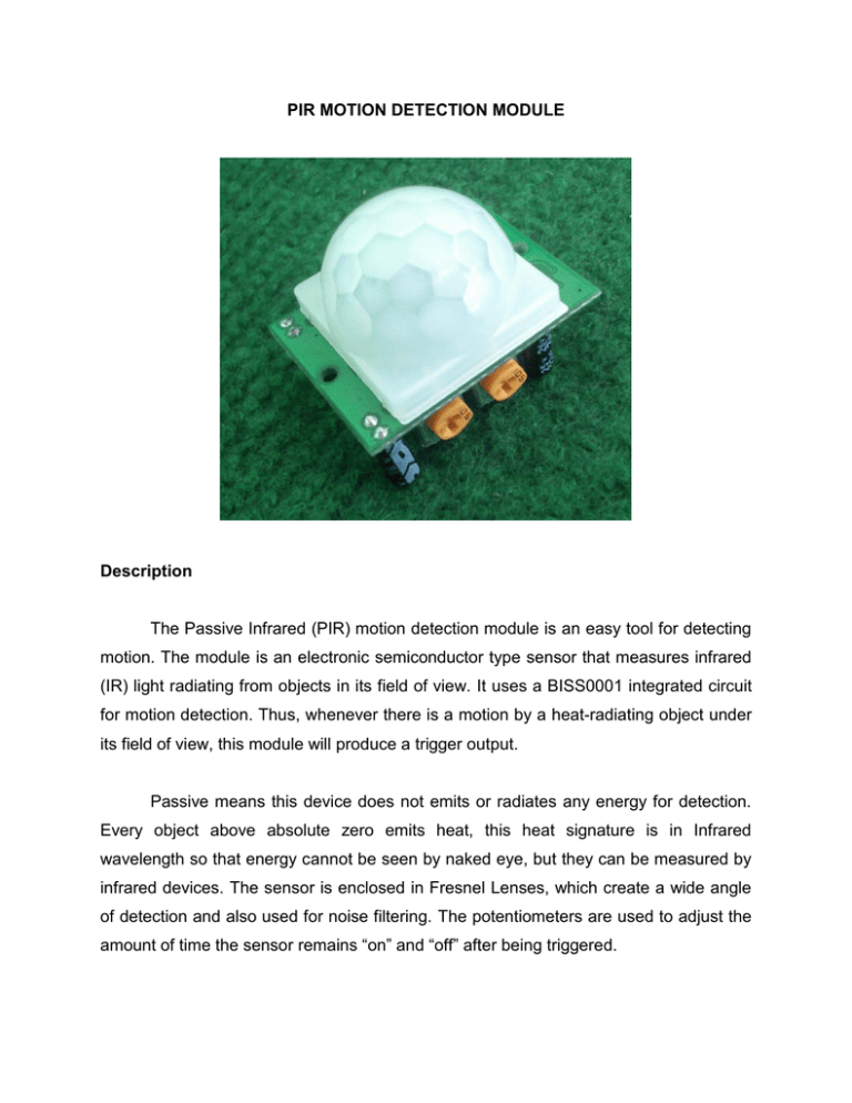
The Passive Infrared (PIR) motion detection module is an easy tool for detecting
motion. The module is an electronic semiconductor type sensor that measures infrared
(IR) light radiating from objects in its field of view. It uses a BISS0001 integrated circuit
for motion detection. Thus, whenever there is a motion by a heat-radiating object under
its field of view, this module will produce a trigger output.
Passive means this device does not emits or radiates any energy for detection.
Every object above absolute zero emits heat, this heat signature is in Infrared
wavelength so that energy cannot be seen by naked eye, but they can be measured by
infrared devices. The sensor is enclosed in Fresnel Lenses, which create a wide angle
of detection and also used for noise filtering. The potentiometers are used to adjust the
amount of time the sensor remains “on” and “off” after being triggered.
Specifications
Use BISS0001 signal processing IC
Voltage: 5V – 20V
Power Consumption: 65mA
TTL output: 3.3V, 0V
Delay time: adjustable (0.3s to 10min)
Lock time: 0.2s
Trigger methods: L – disable repeat trigger, H enable repeat trigger
Non-repeatable trigger/ delay mode (set to LOW): the sensor will turn to low TTL
after the delay, even the sensing object is still in range.
Repeatable trigger (set to HIGH): the sensor will not turn to low if the object still
stays in the sensing range in the delay time.
Sensing range: less than 120 degree, within 7 meters
Temperature: – 15 ~ +70
Dimension: 32x24 mm, distance between screw 28mm, M2, Lens dimension in
diameter: 23mm
Pin Configuration
1
1. VCC: 5V-20V DC
2
3
2. OUT: high/low output
3. GND: ground
Schematic Diagram
Wiring Diagram
12 3
Sample Sketch
void setup(){
Serial.begin(9600);
pinMode(2,INPUT);
}
void loop(){
if(digitalRead(2) == HIGH)
Serial.println("motion detected!");
else
Serial.println(" ");
delay(200);
}
How to test
The components to be used are:
Microcontroller (any compatible arduino)
PIR motion detection module
Pin M-M connectors
Pin F-F connectors
Breadboard
USB cable
1. Connect the components based on the figure shown in the wiring diagram using
M-M and F-F pin connectors. VCC pin is connected to the 5V power supply, GND
pin is connected to the GND and OUT pin is connected to the digital I/O pins. Pin
number will be based on the actual program code.
2. After hardware connection, insert the sample sketch into the Arduino IDE.
3. Using a USB cable, connect the ports from the microcontroller to the computer.
4. Upload the program.
5. See the results in the serial monitor.
Testing results
The serial monitor shows nothing when the module was in standby.
The serial monitor shows that motion is detected when a hand was placed near
the module.


