LCR measurements with Latest LCR head and PSM
advertisement
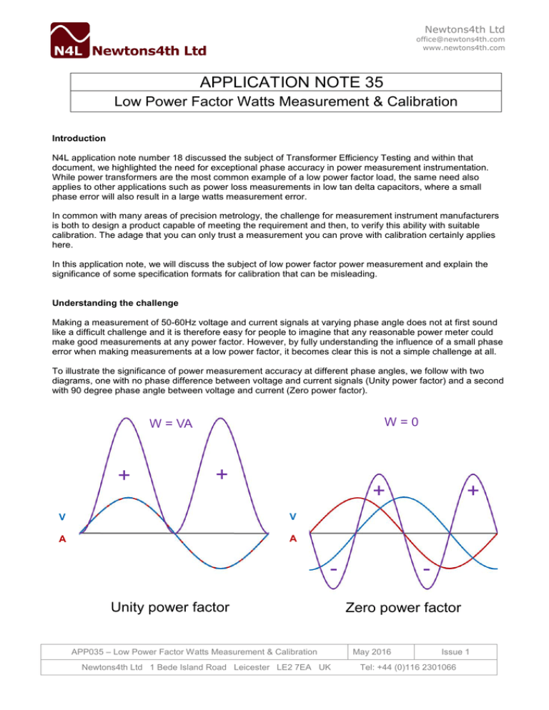
Newtons4th Ltd office@newtons4th.com www.newtons4th.com APPLICATION NOTE 35 Low Power Factor Watts Measurement & Calibration Introduction N4L application note number 18 discussed the subject of Transformer Efficiency Testing and within that document, we highlighted the need for exceptional phase accuracy in power measurement instrumentation. While power transformers are the most common example of a low power factor load, the same need also applies to other applications such as power loss measurements in low tan delta capacitors, where a small phase error will also result in a large watts measurement error. In common with many areas of precision metrology, the challenge for measurement instrument manufacturers is both to design a product capable of meeting the requirement and then, to verify this ability with suitable calibration. The adage that you can only trust a measurement you can prove with calibration certainly applies here. In this application note, we will discuss the subject of low power factor power measurement and explain the significance of some specification formats for calibration that can be misleading. Understanding the challenge Making a measurement of 50-60Hz voltage and current signals at varying phase angle does not at first sound like a difficult challenge and it is therefore easy for people to imagine that any reasonable power meter could make good measurements at any power factor. However, by fully understanding the influence of a small phase error when making measurements at a low power factor, it becomes clear this is not a simple challenge at all. To illustrate the significance of power measurement accuracy at different phase angles, we follow with two diagrams, one with no phase difference between voltage and current signals (Unity power factor) and a second with 90 degree phase angle between voltage and current (Zero power factor). W=0 W = VA + + + V V A A Unity power factor APP035 – Low Power Factor Watts Measurement & Calibration Newtons4th Ltd 1 Bede Island Road Leicester LE2 7EA UK + Zero power factor May 2016 Issue 1 Tel: +44 (0)116 2301066 Newtons4th Ltd office@newtons4th.com www.newtons4th.com It can be understood that the product of voltage and current produces a VA curve and this is shown on these diagrams in purple. VA is commonly referred to as the ‘apparent power’ and at unity power factor, this is equal to the Watts, commonly referred to as ‘real’ or ‘true’ power. As the phase angle between voltage and current changes from zero toward 90 degrees, the apparent power (VA) remains the same because the RMS values of V and A are unchanged but the real power (W) that is represented by the area under the curve tends to zero at zero power factor, where the positive and negative components of real power are exactly equal. We have said that the influence any phase error becomes more significant low power factor and this can easily be illustrated with some simple calculations. Let us consider the influence of a 0.01° phase error at unity power factor (nominal 0° phase angle) and also at a power factor of 0.01 (89.43°) that could easily be experienced in a power transformer loss measurement. For simplicity, we can assume 100Vrms and 10Arms giving 1000VA. We know that W = V x A x Cos Ø so: At unity power factor 1000 x 10 x 1 At 0.01° = 1000W (0.01° phase error) 1000 x 10 x 0.9999 = 999.9W = 0.01% error in measured Watts At 0.01 power factor (89.43°) 1000 x 10 x 9.948x10-3 = 9.948W At 89.44° (0.01° phase error) 1000 x 10 x 9.774x10-3 = 9.774W = 1.75% error in measured Watts So it is clear that any phase error has a significantly greater impact on measured power accuracy when working at a low power factor. It follows that no measurement instrument can maintain the same measured power accuracy at all power factors. Anyone claiming otherwise is either using a misleading method of specification or does not understand the inevitable physics of this application. Low Power Factor Power Accuracy and Calibration Calibration involves the comparison of a measured value with a reference measurement or source of known uncertainty. This process allows an engineer to have confidence in the integrity of measurements being made but of course this has meaning only with regard to the specification being claimed. This is of particular significance for low power factor Watts measurements because the definition of accuracy varies significantly between different instruments. The ideal Watts accuracy specification and associated calibration uncertainty would refer to the total error of measured Watts. This is the method used in our example above and it is clear to a user that at PF 0.01, the Watts accuracy could not be better than 1.75% of the measured value. Unfortunately, in an effort to make accuracy look better than it is, some instrument manufacturers choose to specify low power factor product or calibration accuracy as % of range rather than % of reading. From our example above, the same error for FP 0.01 would be presented as 0.0175% of VA range. This is completely meaningless because any engineer wanting to measure losses in a low power factor application is only interested in % accuracy of the reading NOT the % of some arbitrary range. Conclusion 1. All power measurement instruments will have greater Watts error at low power factor. 2. Users should be wary of any specification for low PF Watts accuracy that refers to % of VA range 3. For low PF applications, users should seek measurement products with traceable % reading accuracy [ Note: The PPA5530-TE from N4L offers a class leading PF 0.01 Watts accuracy of 0.55% total error] APP035 – Low Power Factor Watts Measurement & Calibration Newtons4th Ltd 1 Bede Island Road Leicester LE2 7EA UK May 2016 Issue 1 Tel: +44 (0)116 2301066
