the system presented here will help you avoid personal injury
or damage to property.
Additional and other applicable documents
For further information on the SIU and Lector Viewer operation, please refer to the relevant product manuals.
The SIU manual describes the following aspects in detail:
SIU
for Lector Viewer
• Physical interfaces and pinouts of all connectors
• Installation
• Operation
• Basic functions
The Lector Viewer manual provides a detailed description of
the following application functions:
• System and status information
• Match-code teach-in
• Auto setup
• Parameter switching
• Multi-view
• Sensor-specific configuration settings
The current Quickstart document as well as the manuals and
other documents can be downloaded from the Internet as
follows:
Installation and commissioning
Step 3: Installing the power supply
Scope of delivery
• The power supply may only be installed by a qualified
electrician.
• When working at electrical installations, it is essential
to comply with habitual safety requirements.
The following components and accessories are supplied with
the SIU:
• SD card containing the Lector Viewer installation
• Software license key
• Quickstart document
Step 1: Mounting the SIU
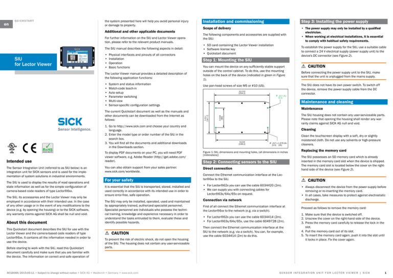
You can mount the device on any sufficiently stable support
outside of the control cabinet. To do this, use the mounting
holes on the back of the device (indicated in green in Figure
1).
Use pan-head screws of size M5 or #10 (US).
10.010
[254.2]
The Sensor Integration Unit (referred to as SIU below) is an
integration unit for SICK sensors and is used for the implementation of system solutions in industrial environments.
The SIU is used to display the results of read operations and
state information as well as for the simple configuration of
camera-based code readers of type Lector®6xx.
The SIU, its accessories and the Lector Viewer may only be
employed in accordance with their intended use. In the case
of any other usage or in the event of any modifications to the
device (e.g. by opening the housing) or to the SICK software,
any warranty claims against SICK AG shall be null and void.
About this document
This Quickstart document describes the SIU for use with the
Lector Viewer and the camera-based code readers of type
Lector®6xx. It contains all the information needed in order to
use the device.
Before starting to work with the SIU, read this Quickstart
document carefully and make sure that you are familiar with
the device. The information on correct and safe operation of
Ø .217 (4x)
[5.5]
9.419
[239.2]
Ø .217 x 1.378 (6x)
[5.5] [35]
You can also obtain support from your sales partner:
www.sick.com/worldwide.
Direct connection
Step 2: Connecting sensors to the SIU
For your safety
Connect the Ethernet communication interface at the Lector®6xx to the SIU.
It is essential that the SIU is transported, stored, installed and
used correctly in accordance with its intended use in order to
ensure error-free, safe operation.
• For Lector®62x you can use the cable 6034420 (2m).
• We can supply you with connecting cables for
Lector®63x/64x/65x on request.
To prevent the risk of electric shock, do not open the housing
of the SIU. The housing does not contain any user-serviceable
parts.
8018084/2015-05-11 • Subject to change without notice • SICK AG • Waldkirch • Germany • www.sick.com
Maintenance and cleaning
Cleaning
Figure 1: SIU, dimensions and mounting holes, (all dimensions in inches
[millimeters])
aa CAUTION
The SIU does not have its own power switch. To switch off
the device, remove the power supply cable from the DC
connector.
The SIU housing does not contain any user-serviceable parts.
Please note that opening the housing shall render any warranty claims against SICK AG null and void.
To display PDF documents on your PC, you will need PDF
viewer software, e.g. Adobe Reader (http://get.adobe.com/
reader).
The SIU may only be installed, operated, used and maintained
by appropriately trained, authorized specialist personnel.
Specialist personnel are individuals who possess the technical training, knowledge and experience necessary in order to
understand the tasks entrusted to them, evaluate these and
identify possible hazards.
aa CAUTION
Before connecting the power supply unit to the SIU, make
sure that the unit is unplugged from the mains supply.
Maintenance
1. Go to http://www.sick.com and choose your country and
language.
2. Enter the model type or order number of the SIU in the
search box.
3. You will find all the documents and additional downloads
in the Downloads section.
Intended use
To establish the power supply for the SIU, use a suitable cable
to connect a 24 V electrical supply (power supply unit) to the
device's DC connector (see Figure 2).
3.543
[90]
Q U I C K S TA R T
5.817
[147.7]
en
Connection via network
First of all connect the Ethernet communication interface at
the Lector®6xx to the network (e.g. via a switch).
• For Lector®62x you can use the cable 6034414 (2m).
• For Lector®63x/64x/65x, use the cable 6049728 (2m).
Then connect the Ethernet communication interface at the
SIU to the network (e.g. via a switch). You can, for example,
use the cable 6034414 (2m) to do this.
Clean the touchscreen display with a soft, dry or slightly
moistened cloth. Do not use any solvents or high-pressure
cleaners.
Replacing the memory card
The SIU possesses an SD memory card which is already
inserted in the memory card slot when the device is shipped.
The memory card slot is located below the cover on the righthand side of the device (see Figure 2).
aa CAUTION
• Always disconnect the device from the power supply before
removing or re-inserting the memory card.
• In all cases, take measures to protect against electrostatic
discharge.
Proceed as follows to remove the memory card:
1. Make sure that the device is switched off.
2. Unscrew the cover on the right-hand side of the device.
3. Press the memory card carefully to release the lock in the
slot.
4. Pull the memory card out of its slot.
5. To insert the memory card again, push it into the slot until
it locks in place. Fix the cover again.
S E N S O R I N T E G R AT I O N U N I T F O R L E C T O R V I E W E R | S I C K
1
Description of the device
Overview of port/connector pinout and design
Device overview and interfaces
DC connector
Ethernet ports
2
2
3
1
2
5
3
1
3
4
Pin
RS232 port
1
4
4
Signal Description
Signal Description
Signal
Description
1
L+
24 V
Tx+
Fieldbus, transmitted signal, positive
Shield
Shield
2
NC
Not connected
Rx+
Fieldbus, received signal, positive
Tx
Send data
3
M
0V
Tx-
Fieldbus, transmitted signal, negative
COM
Common terminal
4
NC
Not connected
Rx-
Fieldbus, received signal, negative
Rx
Receive data
NC
Not connected
5
Analog inputs
2
3
1
4
Analog input 1
Pin
ß
Analog input 2
Signal
Description
Signal
Description
1
+24V out
Power supply +24V
+24V out
Power supply +24V
2
AIN1
Analog input
AIN2
Analog input
3
COM
Common terminal
COM
Common terminal
4
NC
Not connected
NC
Not connected
Digital inputs
Digital outputs
2
2
3
1
3
4
Figure 2: SIU, device overview and interfaces
1 Housing with IP65 enclosure rating
2 LCD touchscreen display
3 Mounting tabs (back plate)
4 Cover for USB ports and memory card slot
5 LED status indicator
6 Ethernet port
7 RS232 port
8 DC power connector
9 Ports 1 and 2 (with analog inputs)
Digital inputs 1 and 2
Pin
1
Signal
Description
+24V out Power supply +24V
1
4
Digital inputs 3 and 4
Digital outputs 1 and 2
Digital outputs 3 and 4
Signal
Description
Signal
Description
Signal
Description
+24V out
Power supply +24V
NC
Not connected
NC
Not connected
2
DIN 1
Sensor input
DIN 3
Sensor input
DOUT 1
Sensor output
DOUT 3
Sensor output
3
COM
Common terminal
COM
Common terminal
COM
Common terminal
COM
Common terminal
4
DIN 2
Sensor input
DIN 4
Sensor input
DOUT 2
Sensor output
DOUT 4
Sensor output
Ports 3 to 6 (with digital inputs and outputs)
2
SENSOR INTEGRATION UNIT FOR LECTOR VIEWER | SICK
8018084/2015-05-11 • Subject to change without notice • SICK AG • Waldkirch • Germany • www.sick.com
The following status LEDs are located on the right-hand side
of the device:
• Power = Power supply
• Ethernet 1 = Ethernet communication
• Ethernet 0 = Ethernet/fieldbus communication
Type
SIU for Lector Viewer
Vibration load
10 Hz to 55 Hz +/- 1 mm, 3 directions
Conformance
UL508, CE
8018084/2015-05-11 ∙ WK_FA ∙ Printed in Germany (2015-05) ∙ All rights reserved ∙ Subject to change without notice
Status display
Service and support
For help and support, please contact one of your partners
in the subsidiary that is responsible for you. You can find
the corresponding contact information on our website under
www.sick.com/worldwide.
References for further information
The copyright notices for open source programs and the associated license texts can be found in the Lector Viewer manual.
Figure 3: Status LEDs
Technical data (extract)
Type
SIU for Lector Viewer
Operating system
Linux 3.6
Processor
ARM (AM3358b), clock frequency: 1 GHz
Working memory
(RAM)
256 MB, extensible to 512 MB
Processing power
2000 Dhrystone MIPS
Data transmission
speed
100 Mbit/s (12.5 MB/s)
Sampling rate
250 kHz
Display
LCD touchscreen display, 7-inch (800
x 480)
Memory card
Capacity: 4 GB, extensible to 32 GB;
Format: microSDHC
Supply voltage
SIU with external power supply: 24 V DC
SIU with integrated power supply: 100 to
250 V AC, 50/60 Hz
Supply current
SIU with integrated power supply: max.
0.8 A
Overvoltage category
II
Protection class
SIU with external power supply: Class II
SIU with integrated power supply: Class I
(protective earth necessary)
7.5 x 5.5 x 2.5 inches
Dimensions
(W x L x H):
Housing material
Aluminum alloy
Weight
3.2 lbs (1.45 kg)
Enclosure rating
IP 65
Ambient temperature,
operation
0…122°F (0…50°C)
Ambient temperature,
storage
-40...167°F (-40...75°C)
Impact load
30 g, 3 directions
8018084/2015-05-11 • Subject to change without notice • SICK AG • Waldkirch • Germany • www.sick.com
S E N S O R I N T E G R AT I O N U N I T F O R L E C T O R V I E W E R | S I C K
3


