Temperature Probe
advertisement

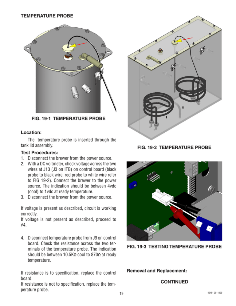
TEMPERATURE PROBE FIG. 19-1 TEMPERATURE PROBE Location: The temperature probe is inserted through the tank lid assembly. FIG. 19-2 TEMPERATURE PROBE Test Procedures: 1. Disconnect the brewer from the power source. 2. With a DC voltmeter, check voltage across the two wires at J13 (J3 on ITB) on control board (black probe to black wire, red probe to white wire refer to FIG 19-2). Connect the brewer to the power source. The indication should be between 4vdc (cool) to 1vdc at ready temperature. 3. Disconnect the brewer from the power source. If voltage is present as described, circuit is working correctly. If voltage is not present as described, proceed to #4. 4. Disconnect temperature probe from J9 on control board. Check the resistance across the two terminals of the temperature probe. The indication should be between 10.5K cool to 870 at ready temperature. If resistance is to specification, replace the control board. If resistance is not to specification, replace the temperature probe. FIG. 19-3 TESTING TEMPERATURE PROBE Removal and Replacement: CONTINUED 19 42461 0911809 TEMPERATURE PROBE 3. Press and hold the "Hidden" button until display reads "CAL TEMPERATURE SENSOR?" "NO/YES" 4. Select "YES". The display should show something similar to the screen below (FIG 20-2). NOTE: Variables such as tank set temperature could show different numbers than the example shown here. Tank must be at it's ready temp before calibrating. 5. Press the + (Control) button to increase or - (Digital) button to decrease temperature reading until it matches the reading on the thermometer. 6. Exit program mode, remove thermometer, and install vent fitting. Calibration is complete Removal and Replacement: 1. Disconnect the brewer from the power source. 2. Disconnect the two pin connector from J9 on control board. 3. Pull temperature probe out of it's grommet. 4. Install in reverse order. Calibration: 1. Remove silicon vent fitting from tank lid. 2. Insert a digital temp probe through the exposed vent hole in tank lid to the same depth as the factory temp probe. FIG 20-1. 200° CAL (-) DONE 200° (+) Adjust this number FIG. 20-2 CALIBRATION FIG. 20-1 CALIBRATE TEMP PROBE 20 42461 0911809


