KM31 Pressure Transmitter
advertisement

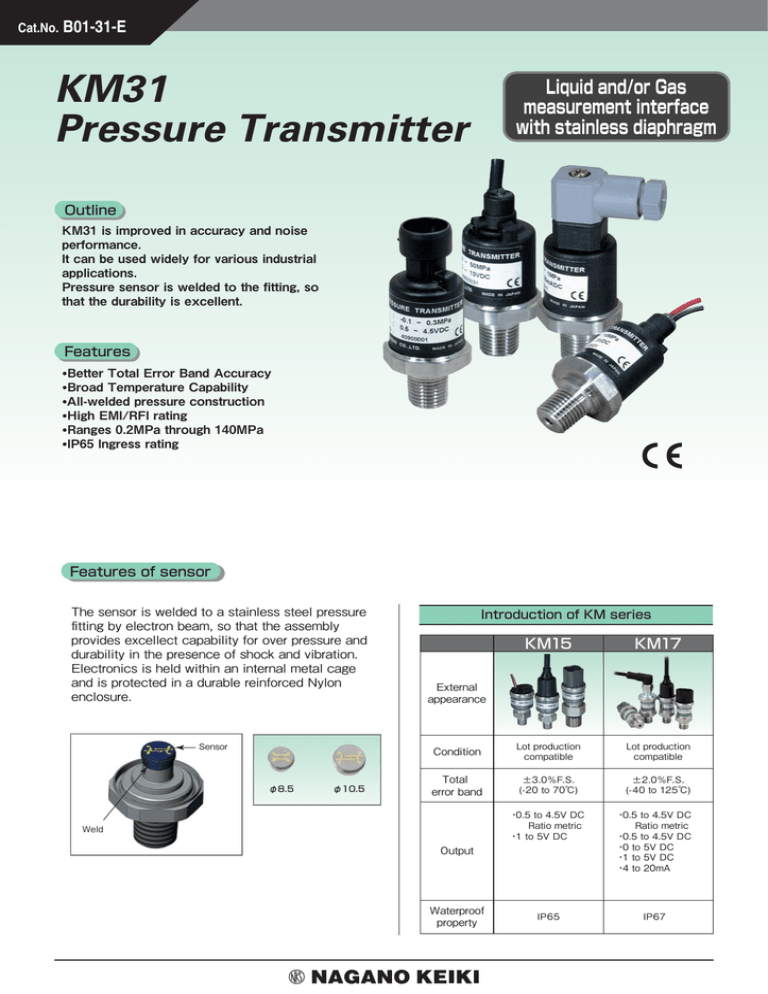
Cat.No. B01-31-E KM31 Pressure Transmitter Liquid and/or Gas measurement interface with stainless diaphragm Outline KM31 is improved in accuracy and noise performance. It can be used widely for various industrial applications. Pressure sensor is welded to the fitting, so that the durability is excellent. Features •Better Total Error Band Accuracy •Broad Temperature Capability •All-welded pressure construction •High EMI/RFI rating •Ranges 0.2MPa through 140MPa •IP65 Ingress rating Features of sensor The sensor is welded to a stainless steel pressure fitting by electron beam, so that the assembly provides excellect capability for over pressure and durability in the presence of shock and vibration. Electronics is held within an internal metal cage and is protected in a durable reinforced Nylon enclosure. Sensor φ8.5 φ10.5 Introduction of KM series KM15 KM17 Condition Lot production compatible Lot production compatible Total error band ±3.0%F.S. (-20 to 70℃) ±2.0%F.S. (-40 to 125℃) External appearance Weld ・0.5 to 4.5V DC Ratio metric ・1 to 5V DC ・0.5 to 4.5V DC Ratio metric ・0.5 to 4.5V DC ・0 to 5V DC ・1 to 5V DC ・4 to 20mA IP65 IP67 Output Waterproof property KM31 Pressure Transmitter Specifications Pressure range (MPa) Gauge pressure Measuring range Output signal -0.1 -0.1 -0.1 -0.1 -0.1 0 0 0 0 0 0 0 0 0 0 0 0 0 0 to to to to to to to to to to to to to to to to to to to Withstand pressure 0.2 0.3 0.5 1 2 0.2 0.3 0.5 1 2 3.5 5 10 20 35 50 70 100 140 Error outside above temperature range (-40 to -20℃) ±1.5%F.S. (85 to 125℃) ±1.5%F.S. 150% 120% Output range Supply voltage Maximum supply voltage 0.5 to 4.5V DC Ratio metric 5.0±0.5V DC 16V DC maximum Transmission method 0 to 5V DC 1 to 5V DC 9 to 36V DC 0 to 10V DC Withstand voltage Insulation resistance 3 wire system 36V DC maximum 14 to 36V DC 4 to 20mA DC Material Linearity ±0.25%F.S. Total Error Band (-20 to 85℃) ±1.0%F.S. It includes the following ①Linearity ②Hysteresis ③Repeatability 200% of pressure range 1 to 6V DC Environmental performance Accuracy 2 wire system 9 to 36V DC * 100V AC (1 minutes between fitting and all terminals tied) 100MΩ or higher (100V DC between fitting and all terminals tied) Output response 1ms or lower Circuit protection Reverse polarity and mis-wire protected Compensated temperature range Operating temperature range Storage temperature range -40 to 125℃ (Except connector 3 / DIN43650-A and cable are -30 to 105℃) Shock proof 981m/s2 (6ms or lower) Vibration proof Based:196.1m/s2 rms Durability 50,000,000 times or higher (10 to 100%F.S.) Protection IP65 Diaghragm SUS630 (17-4PH), Welded to a pressure fitting Fitting SUS304 Case Nylon 66 R1/8 R1/4 Maximum allowable pressure: 50MPa R3/8 Fittings Terminations Weight G1/4A Maximum allowable pressure: G3/8A Maximum allowable pressure: 50MPa 5MPa G1/4B Maximum allowable pressure: 140MPa 7/16-20UNF Maximum allowable pressure: 20MPa Connector 1 METRI-PACK 150 series Connector 2 Mini-Hirschmann G series Connector 3 DIN43650-A Leads Flying leads 1m (Standard) Cable Shielded cable 1m (Standard) Approx. 65g (METRI-PACK 150 series, R1/4, without mating connector) (Note) When the load resistance 500 Ω or more are needed, the loop supply voltage of 20V DC or more is necessary. Sealed pressure type is available for 5MPa range or greater. 2 KM31 Pressure Transmitter Explanation of the loop resistance and accuracy Loop Resistance at 2 wire system 4 to 20mA DC output 【About the total error band】 In case of presupposing to use in wide temperature range, it is common to define error by total error band shown bellow. The graph shows allowable error band in entire operating temperature range. The output will be within the indicated allowable error band even if ambient temperature varies. 1 to 1.5%F.S. Total error band is accomplished by incorporating high performance ASIC to very stable poly-silicon thin film that is proven in the field. Minimum loop supply voltage=9(V)+(0.022(A) x RL) Maximum loop supply voltage=24(V)+(0.024(A) x RL) RL = RS+RW RS = Sense Resistance (Ω) RW = Wiring Resistance (Ω) 1400 1227 1200 1000 Loop Resistance RL (Ohms) Total Errer Band Description 3.0% 800 2.5% 600 2.0% 500 400 1.5% OPERATING REGION 200 1.0% Allowable Accuracy 0 10 20 30 9 (Minimum) 24 40 0.5% 0.0% -0.5% −1.0% 36 (Maximum) −1.5% Loop Supply Voltage (V DC) −2.0% −2.5% −3.0% −40 When the load resistance 500 Ω or more are needed, the loop supply voltage of 20V DC or more is necessary. −20 0 20 40 60 80 100 120 125 Temperature DIN 43650-A Dimensions 2 3 Unit: mm Mini-Hirschmann G Series compatible 2 3 3 1 2 Case ground METRI-PACK 150 Series compatible Wiring Connector type 2 wire system 1 :── Power (+) 2:── Power (-) 2 1 Mating connector (36) 3 33.5 5.73 Label 27 Hex. 2* R1/8 KM31-364 Cable wiring Shielded cable 2 wire system 1 :Red ─ Power (+) 2:Black ─ Power (-) 5.73 (45) 2* 27 Hex. * ** ** R1/8 KM31-464 φ24 Marking Label 27 Hex. * ** ** R1/8 10* (45) 5.73 Label 10* *Dimentions above are for R1/8 fitting. Please refer following table for the othte fittings. φ24 Marking 2* 10* R1/8 KM31-164 Mating connector φ24 *** L (Standard 1m) 27 Hex. * ** ** AEX28 0.5mm2 3 wire system 1 :── Power (+) 2:── Common 3:── Output (+) Marking 10* R1/8 KM31-264 L (Standard 1m) 5.73 2* Label 27 Hex. * ** ** 10* (8) (52) φ24 Marking (52) Label 2* Mating connector φ24 Marking 5.73 (57) AEX28 0.5mm2 (40) (88) 2 (53) 1 4 Case ground L (Standard 1m) 3 1 1 3 wire system 1 :Red ─ Power (+) 2:Black ─ Common 3:White ─ Output (+) ※Shield is not connected KM31-564 to case ground. Process fitting G1/4A JIS B2401 Class 1B φ3.3 G1/4B φ4.5 60° Maximum allowable pressure: 50MPa (Include R1/8) Maximum allowable pressure: 5MPa 7/16-20UNF φ5.5 φ9.2 G3/8A Maximum allowable pressure: 50MPa 3 φ5 3.7 O-ring P14 JIS B2401 Class 1B 14 16 φ14±0.1 16 2 12 18 14 O-ring P11 KM31-□54 45° R1/4 R3/8 2.7 φ11±0.1 KM31-□24 2 KM31-□C4 3 KM31-□B4 2.7 KM31-□84 2 KM31-□74 Maximum allowable pressure: 140MPa Maximum allowable pressure: 20MPa KM31 Pressure Transmitter Model number configuration Please specify the model number, each specs and the range for ordering. Model 4 K M 3 1 Pressure Transmitter ① ② 7 ③ ④ ⑤ ⑥ ⑦ ⑧ Selective spec. Model number ⑨ ⑩ ⑪ ⑫ ⑬ ⑭ ⑮ Additional spec. (Option) Gauge pressure type (Standard) ① Type 1 Connector 1 (METRI-PACK) 2 Connector 2 (Mini-Hirschmann) *1 3 Connector 3 (DIN43650-A) 4 Leads type (1m Standard) 5 Cable type (1m Standard) *1 Sealed pressure type (Pressure range: 5MPa or higher) J Connector 1 (METRI-PACK) K Connector 2 (Mini-Hirschmann) *1 L Connector 3 (DIN43650-A) M Leads type (1m Standard) N Cable type (1m Standard) ② Process fitting *1 Fitting standard Maximum allowable pressure 2 G1/4B 140MPa 5 7/16-20UNF 20MPa 6 R1/8 50MPa 7 R1/4 (Standard) 50MPa 8 R3/8 50MPa B G1/4A C G3/8A (Standard) 5MPa 50MPa Consult sales office for the other options. ③ Wetted parts material Please specify applicable range code as well as pressure range and engineering unit. 4 Diaghragm: SUS630 (17-4PH) Fitting: SUS304 ④ Pressure range (MPa) 2 -0.1 to 0.2 B 0 to 0.2 K 0 to 3.5 S 3 -0.1 to 0.3 C 0 to 0.3 L 0 to 5 T 0 to 70 5 -0.1 to 0.5 E 0 to 0.5 N 0 to 10 U 0 to 100 6 -0.1 to 1 G 0 to 1 Q 0 to 20 V 0 to 140 7 -0.1 to 2 J 0 to 2 R 0 to 35 7 ⑤ Accuracy Total Error Band±1.0%F.S. (-20 to 85℃) (Includes Linearity, Hysteresis, Repeatability) ⑦ Output signal (Supply voltage) Y 0.5 to 4.5V DC Ratio metric 3 wire (5.0±0.5V DC) 6 0 to 5V DC 3 wire system (9 to 36V DC) 8 1 to 5V DC 3 wire system (9 to 36V DC) Z 1 to 6V DC 3 wire system (9 to 36V DC) 7 0 to 10V DC 3 wire system (14 to 36V DC) 1 4 to 20mA DC 2 wire system (9 to 36V DC) ⑧ Optional 0 No mating conn 1 Cabel / Leads 1m (Standard) 9 Specify Wire length ⑨ Treatment *1 Cable with connector on the other side are not included. *Lead type lead length can cope with it from 0.5 to 5m. (0.5m units) *Shielded cable type cable length can cope with it from 1 to 5m. (0.5m units) *For special length, please contact separately. Metri-Pack is a trademark of Delphi Packard Electronics System. Mini-Hirschmann is a trademark of Richard Hirschmann of America, Inc.. Treatment of wetted parts ■Use no oil Oil used in manufacturing the gauges had been flushed out & no oil residue remained inside its wetted parts. ■Use no water Water used in manufacturing the gauges had been flushed out & no water residue remained inside its wetted parts. ■Use no oil & water Oil/Water used in manufacturing the gauges had been flushed out & no oil/water residue remained inside its wetted parts. *Specify by code "X" if there is no applicable specification. 4 0 to 50 ⑮ Documents 0 Nil 1 Use no oil 2 Use no water 3 Use no oil & water 0 1 Nil Required (Please specify the desired documents separately.) Submission drawings, instruction manual, test report (1 pc 1 copy), inspection/traceability certificate


