Feedback in Operational Amplifiers
advertisement
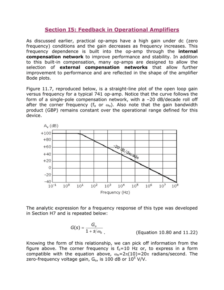
Section I5: Feedback in Operational Amplifiers As discussed earlier, practical op-amps have a high gain under dc (zero frequency) conditions and the gain decreases as frequency increases. This frequency dependence is built into the op-amp through the internal compensation network to improve performance and stability. In addition to this built-in compensation, many op-amps are designed to allow the selection of external compensation networks that allow further improvement to performance and are reflected in the shape of the amplifier Bode plots. Figure 11.7, reproduced below, is a straight-line plot of the open loop gain versus frequency for a typical 741 op-amp. Notice that the curve follows the form of a single-pole compensation network, with a –20 dB/decade roll off after the corner frequency (fo or ωo). Also note that the gain bandwidth product (GBP) remains constant over the operational range defined for this device. The analytic expression for a frequency response of this type was developed in Section H7 and is repeated below: G(s) = Go 1 + s ω0 . (Equation 10.80 and 11.22) Knowing the form of this relationship, we can pick off information from the figure above. The corner frequency is fo=10 Hz or, to express in a form compatible with the equation above, ωo=2π(10)=20π radians/second. The zero-frequency voltage gain, Go, is 100 dB or 105 V/V. Just as a little heads-up here – a logarithmic plot will never actually go to zero, but we call the value of the flat portion of the plot the zero frequency parameter. So, putting this all together, the analytic expression that describes the specific behavior of Figure 11.7 is 10 5 G(s) = 1 + s 20π . Prove to yourself that this is true. For frequencies more than a decade below 20π the magnitude of G(s) is approximately 105 (remember that s=jω). At 5 2 or –3 dB, and for frequencies greater 20π, the magnitude becomes 10 than 20π, the magnitude decreases at a rate of 20 dB/decade. To illustrate the effect of feedback on operational amplifier circuits, we will begin with the inverting amplifier circuit of Figure 11.8a (to the right). To make sure that we are focusing on error that may be introduced due to gain variations, all characteristics of the op-amp are considered ideal except for the variation of gain with frequency. To find the effect of the output voltage on the opamp input, we look at the ratio v-/vo, where v- is a function of vin and vo. We will also assume that the input signal (vin) is equal to zero since we are interested in only the portion of v- that is due to vo. From Section H7, we defined a feedback attenuation factor γ and the low-frequency gain of the non-inverting op-amp to be 1/γ where, in terms of purely resistive components, γ = RA 1 = R A + RF 1 + RF RA . (Equation 11.23) This function represents the fraction of the output voltage that is fed back to the inverting terminal with vin=0. To prove this statement, we can write the KCL equation at v- (remember that vin=0) v − − v in v − − v o + =0 RA RF . (Equation 11.25) Solving for v-, we obtain v− = R Av o vo = R A + RF 1 + RF = γv o RA . (Equation 11.24) Note: there is some inconsistency in your text with the generic terms Go and G. The way these have been defined, and we’ve been using, is Go indicates the open-loop op-amp gain and G is the closed-loop gain (i.e., with feedback) that is usually frequency dependent. I have modified several equations to reflect these definitions, but if there’s any question, please let me know. In the figure above, the non-inverting terminal is tied to ground so v+=0. Using the gain relationship for ideal op-amps from last semester in terms of the open-loop gain Go and the difference seen at the two input terminals, i.e., v o = Go (v + − v − ) , v- can be expressed in terms of Go and vo as v− = − vo Go . (Equation 11.26) Substituting Equation 11.26 into Equation 11.25 (keeping vin this time), rearranging to get in the form vo/vin, we get the expression for the closed loop voltage gain (expressed in the familiar AV) of the inverting op-amp circuit to be Av = vo − RF = vi n RA ⎛ 1 ⎜⎜ ⎝ 1 + (1 + RF R A ) / G o ⎞ − RF ⎟⎟ = RA ⎠ ⎛ γG o ⎜⎜ ⎝ 1 + γG o ⎞ ⎟⎟ ⎠ , (Eqns 11.27 & 11.28) where the feedback attenuation factor, γ, was incorporated into the last relationship. As the op-amp gain increases, or we look at the limit as Go→∞, the expressions in Equation 11.27 or Equation 11.28 goes to the gain expression for an ideal inverting op-amp configuration, or Av ∞ = − RF RA . (Equation 11.29) This means that as the op-amp gain gets very large, the closed-loop gain becomes independent of the value of Go and becomes a function of the two resistor values RF and RA (or ZF and ZA if complex impedances are used). A similar analysis was performed in Section H7 for the non-inverting configuration, or may be derived using the procedure above with the result Av = Go 1 + Go γ . (Equation 11.32, Modified) In the limit that Go→∞, the gain of the non-inverting configuration becomes Av∞ = 1 γ = R A + RF R =1+ F RA RA , (Equation 11.33) which is the gain expression for the ideal op-amp non-inverting circuit. The two gain expressions, Equations 11.28 and 11.33, can be normalized by dividing each closed loop gain, Av, by the appropriate Av∞. After normalizing, the same expression results for both the inverting and non-inverting configurations: Av = Go γ 1 + Go γ , (Equation 11.34) where Equation 11.34 is in the form of the generic closed loop feedback system discussed in Section I2 and Goγ is the loop gain of Equation 11.3. Note that the loop gain of both amplifier configurations is the same. To determine the sensitivity of the closed-loop gain, Av, to changes in the loop gain, Goγ, we follow the approach defined in Section I3; i.e., differentiate Av with respect to Goγ, then divide by Av and rearrange to obtain d(G o γ ) d (G o γ ) dAv 1 = = Av (G o γ )(1 + G o γ ) 1 + G o γ G o γ . (Equation 11.36) Equation 11.36 applies to both the inverting and non-inverting amplifier configurations and clearly shows the effect of feedback. Any variation in the loop gain, Goγ, is divided by Goγ (1+ Goγ) and results in a much smaller variation in the closed loop gain. So… just as in the case of discrete component amplifiers, op-amps exhibit less sensitivity when feedback is used.


