Installation Instructions for
920E3HEH-LNIC
Round or Square Type Low-Profile Housing
with Electronic Transformer for Flangeless Trims
E3_LF-HDSE-WR_
1.0
HALOGEN MR16 - ROUND/SQUARE FLANGELESS
GENERAL PRODUCT INFORMATION:
This product is suitable for indoor locations.
This product can be dimmed with a standard electronic dimmer.
This instruction shows a typical installation.
CAUTION - RISK OF FIRE
This product requires installation by a qualified
electrician. Before installing be sure to read all
instructions and TURN OFF POWER TO THE
ELECTRICAL BOX.
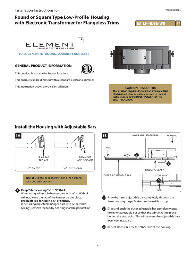
Install the Housing with Adjustable Bars
1A
1B
INNER ADJUSTABLE BAR
HOUSING
NAIL
3
LEAVE TAB
IN PLACE
BREAK OFF
AND DISCARD
2
½” to ¾”
¾” or thicker
HOUSING CLASP
OUTER ADJUSTABLE BAR
NOTE: Skip this section if installing the housing
3
with butterfly brackets.
1
STOP POINT
TAB
Keep Tab for ceiling ½” to ¾” thick.
When using adjustable hanger bars with ½” to ¾” thick
ceilings, leave the tab of the hanger bars in place.
Break off Tab for ceiling ¾” or thicker.
When using adjustable hanger bars with ¾” or thicker
ceilings, remove the tab by bending it at the perforation.
1
2
Slide the inner adjustable bar completely through the
three housing clasps. Make sure the nail is on top.
3
Slide and push the outer adjustable bar completely onto
the inner adjustable bar so that the tab clicks into place
behind the stop point. This will prevent the adjustable bars
from coming apart.
4
Repeat steps 2 & 3 for the other side of the housing.
1C
1D
NAIL
ADJUSTABLE BAR
HOUSING
7
6
6
5
5
TRIM HOLDER
NAIL
JOIST
TRIM HOLDER
NOTCH
6
8
5
NOTCH
NOTE: The adjustable bars can be mounted to
joists that are spaced 16" - 24" apart.
5
6
HOUSING
Align the bottom of the end plates with the bottom of the
ceiling joists.
TRIM HOLDER
Level the adjustable bars and, with a hammer, tap the nails
completely into the joists to secure the adjustable bars in
place.
#6 SELF TAPPING SCREW
8
7
Adjust the trim holder position (horizontal position) by
sliding the housing on adjustable bars.
8
When the desired location is achieved, tighten the two #6
self tapping screws to lock the housing onto the adjustable
bars.
NOTE: Notches in trim holder can be used to
align multiple housings using a laser or string.
2
Install the Housing with Butterfly
Brackets
2A
2C
BUTTON HEAD SCREW
BUTTERFLY
BRACKET
1
SLOT
WING
NUT
6
4
NOTE: Skip this section if installing the housing
with adjustable bars.
5
Place the button head screw through the square cut out of
the butterfly bracket into the housing slot.
1
2B
SUPPORT BRACKET CENTER HOLE
BUTTERFLY
BRACKET
3
2
4
Attach the wing nut loosely to the button head screw.
5
Slide the butterfly bracket up or down to achieve the
proper location. Tighten the wing nut to secure the
butterfly bracket in place.
6
Repeat steps 1-5 for the other butterfly bracket.
7
Use the butterfly brackets to install the housing in
accordance with local building and electrical codes.
NOTE: Notches in trim holder can be used to
align multiple housings using a laser or string.
BUTTON
HEAD SCREW
SUPPORT BRACKET SLOT
2
Place the support bracket center hole onto the button
head screw.
3
Push the support bracket slots against the butterfly
bracket tabs.
3
Connect Power to the Housing
3C
3A
TRANSFORMER
TAB
ELECTRICAL
BOX COVER
6
1
5
4
THERMAL
PROTECTOR
1
Push the tab on the housing electrical box up and remove
the electrical box cover.
4
Connect the neutral power line wire to the white
transformer wire and the white thermal protector wire with
the wire nut.
5
Connect the hot power line wire to the black thermal
protector wire with the wire nut.
6
Connect the fixture ground wire and the green transformer
wire to a suitable ground according to local electrical
codes.
3B
CONDUIT
2
3
3D
TAB
ELECTRICAL
BOX COVER
7
2
Install the conduit to the housing electrical box.
3
Run the power line wires into the housing electrical box.
7
WARNING: RISK OF FIRE: When using the
housing electrical box for power feed through,
use MAX 4 - #12 AWG, or 6 - #14 AWG branch
circuit wires.
4
Replace the electrical box cover. Make sure that the top
edge of the cover snaps under the tab.
Install Drywall and Plaster Ring
4B
4A
3-7/8"
3-7/8"
2
DRYWALL
ROUND TRIM HOLDER
2
1
TRIM HOLDER
JOIST
SQUARE TRIM HOLDER
For round trims, mark a 3-7/8" diameter circle on drywall.
Cut out the marked section.
For square trims, mark a 3-7/8" square on drywall. Cut out
the marked section.
Align the cut out section of drywall with the trim holder
and install the drywall.
WARNING: Risk of Fire: The housing is not
intended to be in contact with or covered with
combustible materials and insulation. Do not
install insulation within 3 inches of the housing
sides or above in such a manner to entrap heat.
5
4C
TAB
4D
TAB
3
3
3
3
#8-32 SCREW
#8-32 SCREW
5
5
5
ROUND PLASTER RING
5
SQUARE PLASTER RING
5
Secure the plaster ring in place with the two provided flat
head #8-32 screws. Make sure that the screws penetrate
through the drywall into the housing screw holes.
NOTE: Do not overtighten the screws!
Overtightening may bend the plaster ring,
causing the plaster surface to come away from
the drywall.
4
3
3
CUT OUT
4
4E
3
3
6
CUT OUT
6
3
Line up the two tabs in back of the plaster ring with the
two cut out sections of the trim holder inside edge.
4
Push the plaster ring tabs into the cut out sections of the
trim holder edge.
6
Plug the trim holder with the provided dust shield.
7
Properly plaster onto the plaster ring and drywall.
4F
6
8
Finish around the trim to match drywall.
LENS LOCK
8
LENS LOCK
8
Adjust the Lamp Housing
6B
6A
LAMP HOLDER
SPRING
LAMP
LENS
LAMP HOLDER
1
3
Ensure that the glass lens is properly inside the lamp
holder.
4
Slide the lamp completely into the lamp holder spring so
the lamp snaps into the lamp holder.
6C
Ensure that the lamp housing is centered to the aperture
by pulling it to the center of the housing. When centered
the locking pin will be engaged.
LAMP ASSEMBLY
Install the Lamp
6A
KEYED SLOT
1
LAMP HOUSING
KEYED SLOT
SOCKET WIRE SLEEVE
SOCKET
2
LAMP
Use MAX 50 Watt Type MR16 Halogen
Lamp.
1
Pull the socket out of the housing.
2
Push the lamp pins completely into the socket holes.
7
5
Feed the socket wire sleeve back into the lamp housing
and align the lamp assembly with the keyed slots on the
lamp housing.
6
Place the lamp assembly into the lamp housing and rotate
it until it locks into place.
IMPORTANT SAFETY INSTRUCTIONS
Halogen Lamp General Information
To reduce the risk of fire, electrical shock, exposure to excessive
UV radiation, or injury to person:
– It is normal for a new halogen lamp to smoke slightly
on first use. The protective coating is being vaporized.
– Use this fixture indoors only.
– Do not look directly at the lighted lamp.
Prolonging Halogen Lamp Life
– Do not remain in light if skin feels warm.
– Do not touch the lamp with bare hands. Any contaminant,
even the oil from your hands can deteriorate the lamp.
Handle the lamp with a soft, clean cloth. Rubbing alcohol
can be used to remove any contaminant from the lamp.
– Risk of fire: Use only the type of lamp and maximum
wattage indicated in this instruction manual.
– Do not run the lamps at full power when you do
not need to. However, if dimming the fixture for an
extended period of time, occasionally bring the light up to
full brightness for a few minutes to complete the halogen
cycle.
– Never cover the halogen lamp with anything other than a
Element Lighting lamp shield and never place flammable
material close to your fixture.
– Do not touch the fixture shades or lamp shield while the
fixture is on. These surfaces may be HOT.
– To avoid glare in child's eyes, hang the fixture at least 18”
above a table.
SAVE THESE INSTRUCTIONS!
7400 Linder Ave, Skokie, IL 60077
847.410.4400
www.element-lighting.com
© 2012 Element Lighting, L.L.C. All rights reserved. The "Element" graphic
is a registered trademark of Element. Element reserves the right to
change specifications for product improvements without notification.
A Generation Brands Company
8


