iC-LNG EVAL LNG2M-xR EVALUATION KIT DESCRIPTION - iC-Haus
advertisement

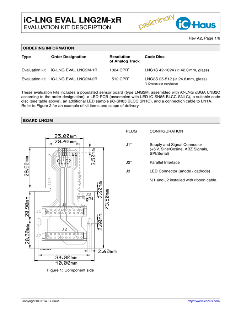
ar y n i im prel iC-LNG EVAL LNG2M-xR EVALUATION KIT DESCRIPTION Rev A2, Page 1/6 ORDERING INFORMATION Type Order Designation Resolution of Analog Track Code Disc Evaluation kit iC-LNG EVAL LNG2M-1R 1024 CPR* LNG1S 42-1024 (∅ 42.0 mm, glass) Evaluation kit iC-LNG EVAL LNG2M-2R 512 CPR* LNG2S 25-512 (∅ 24.8 mm, glass) *) Cycles per revolution These evaluation kits includes a populated sensor board (type LNG2M, assembled with iC-LNG oBGA LNB2C according to the order designation), a LED-PCB (assembled with LED iC-SN85 BLCC SN1C), a suitable code disc (see table above), an additional LED sample (iC-SN85 BLCC SN1C), and a connection cable to LN1A. Refer to Figure 2 for an example of kit items and scope of delivery. BOARD LNG2M PLUG CONFIGURATION J1* Supply and Signal Connector (+5 V, Sine/Cosine, ABZ Signals, SPI/Serial) J2* Parallel Interface J3 LED Connector (anode / cathode) *J1 and J2 installed with ribbon cable. Figure 1: Component side Copyright © 2014 iC-Haus http://www.ichaus.com iC-LNG EVAL LNG2M-xR EVALUATION KIT DESCRIPTION ar y n i im prel Rev A2, Page 2/6 OVERVIEW OF KIT ITEMS Figure 2: Scope of delivery: LED PCB, LED sample, sensor board with ribbon cable and code disc (hub not included). RELATED PRODUCTS AND DOCUMENTATION Item Description iC-LNG oBGA LNB2C-xR 16-Bit optical encoder with SPI and serial/parallel outputs Documentation and Information http://www.ichaus.de/ product/iC-LNG LNG1S 42-1024 Code disc suitable for iC-LNG equipped with reticle LNG1R (iC-LNG oBGA LNB2C-1R) LNG2S 25-512 Code disc suitable for iC-LNG equipped with reticle LNG2R (iC-LNG oBGA LNB2C-2R) iC-LNG EVAL LN1A Microcontroller board suitable for LNG2M iC-SN85 BLCC SN1C High-Quality encoder IR LED, 850 nm, with lens, SMT http://www.ichaus.de/ product/iC-SN85 iC-MB3 iCSY MB3U-I2C BiSS/SSI and I2 C-to-PC adapter (USB) http://www.ichaus.de/ product/MB3U-I2C ar y n i im prel iC-LNG EVAL LNG2M-xR EVALUATION KIT DESCRIPTION Rev A2, Page 3/6 CONNECTOR AND TERMINAL PINOUT J1: Sine/Cosine and ABZ Signals, Serial/SPI Interfaces, Supply Voltages PIN Name Function 1 INCZ Incremental Output Z 2 INCB Incremental Output B 3 INCA Incremental Output A 4 ERR Error Message Output 5 NCOS Analog Voltage Output Cosine 6 PCOS Analog Voltage Output Cosine + 7 NSIN Analog Voltage Output Sine 8 PSIN Analog Voltage Output Sine + 9 n.c. 10 VDDA +4 V to +5.5 V Supply Voltage 11 GND Ground 12 VDD +3 V to +5.5 V I/O Port Supply Voltage 13 SCK SPI Clock Input 14 MOSI SPI Data Input 15 MISO SPI Data Output 16 CS SPI Chip Select 17 NSL Shift Register Load 18 DIN Shift Register Data Input 19 DOUT Shift Register Data Output 20 CLK Shift Register Clock J3: 2-pin LED Connector PIN Name Function 1 LED LED Anode 2 LED_C LED Cathode J2: Parallel Output Signal PIN 1 2 3 4 5 6 7 8 9 10 11 12 13 14 15 16 17 18 19 Name TPC TPS INCA INCB INCZ POK PO5 PO6 n.c. CLK DOUT DIN NSL n.c. TNS TNC VDDA GND VDD 20 LED Function Parallel Output Bit 0 Parallel Output Bit 1 Parallel Output Bit 2 Parallel Output Bit 3 Parallel Output Bit 11 Parallel Output Bit 4 Parallel Output Bit 5 Parallel Output Bit 6 Parallel Output Bit 7 Parallel Output Bit 8 Parallel Output Bit 9 Parallel Output Bit 10 Parallel Output Bit 12 Parallel Output Bit 13 +4 V to +5.5 V Supply Voltage Ground +3 V to +5.5 V I/O Port Supply Voltage LED Current Control (Highside Output) ar y n i im prel iC-LNG EVAL LNG2M-xR EVALUATION KIT DESCRIPTION Rev A2, Page 4/6 CIRCUIT SCHEMATIC 19 J2 12 J1 10 J1 17 J2 The iC-LNG sensor board LNG2M features two 20-pin ribbon cables for the IC’s interfaces (serial, parallel, ABZ, SinCos) and a two-pin connector for the LED (suitable for iC-SN85 EVAL SN1M). The two ribbon cables connect to the microcontroller board LN1A (see Figure 4). C1 100nF J3 2 U1 iC-LNG R1 47 C2 100nF A5 VDDA LED-Control J3 1 VDD Calibration sin2+cos2, sum A4 LED J2 20 A2 PSIN B6 Cosine Sine PCOS B4 NSIN B5 P NCOS C6 N 8 6 7 5 J1 J1 J1 J1 13 14 15 16 J1 J1 J1 J1 Interpolation sin iC-LNG dig J1 1 J2 5 SIN J1 20 J2 10 TRACK9 D3 D2 D1 E3 NSL DIN DOUT CLK TRACK7 TRACK6 TRACK5 TRACK4 TRACK3 TRACK2 TRACK1 GNDA GND A6 A3 Figure 3: Circuit diagram LNG2M PAR TPC TNC TPS TNS SPI TRACK8 C5 C3 C4 C2 J1 11 J1 19 J2 11 TRACK11 TRACK10 J2 18 J1 18 J2 12 1 16 2 15 TEST J1 17 J2 13 J2 J2 J2 J2 SER J1 2 J2 4 COS LOGIC C1 INCZ D5 INCA D4 INCB J1 3 J2 3 SCK MOSI MISO CS A1 B3 B2 B1 PO6 E2 PO5 E5 8 J2 7 J2 POK E6 ERR D6 6 J2 4 J1 iC-LNG EVAL LNG2M-xR EVALUATION KIT DESCRIPTION ar y n i im prel Rev A2, Page 5/6 ASSEMBLY PART LISTS Device C1, C2 R1 U1 J1, J2 Value (typical) 100 nF 47 Ω iC-LNG oBGA LNB2C-xR 20 pol. J3 2 pol. Comment Capacitors LED current limiting series resistors Optical position encoder IC with reticle LNGxR PCB Crimp connector assembled with 25 cm ribbon cables LED connector (female) suitable for SN1M Table 1: Board LNG2M Device U1 J1 Value (typical) iC-SN85 BLCC SN1C 2 pol. Comment High-end IR encoder LED (850nm) LED connector (male) suitable for LNG2M Table 2: Board SN1M APPLICATION EXAMPLE Figure 4: iC-LNG eval kit parts Required eval kit parts: 1. iC-LNG EVAL LNG2M-xR (for x pls. ref. to the ordering designation) 2. iC-LNG EVAL LN1A 3. iC-MB3 iCSY MB3U-I2C iC-LNG EVAL LNG2M-xR EVALUATION KIT DESCRIPTION ar y n i im prel Rev A2, Page 6/6 Figure 5: Encoder test application with iC-LNG EVAL LNG2M-xR REVISION HISTORY Rel Rel.Date A1 11-09-28 Chapter Modification Page Rel Rel.Date Chapter Modification Page A2 14-06-10 ORDERING INFORMATION New order designation iC-LNG EVAL LNG2M-2R 1 Inital Release Chapters new arranged iC-Haus expressly reserves the right to change its products and/or specifications. An info letter gives details as to any amendments and additions made to the relevant current specifications on our internet website www.ichaus.de/infoletter; this letter is generated automatically and shall be sent to registered users by email. Copying – even as an excerpt – is only permitted with iC-Haus’ approval in writing and precise reference to source. iC-Haus does not warrant the accuracy, completeness or timeliness of the specification and does not assume liability for any errors or omissions in these materials. The data specified is intended solely for the purpose of product description. No representations or warranties, either express or implied, of merchantability, fitness for a particular purpose or of any other nature are made hereunder with respect to information/specification or the products to which information refers and no guarantee with respect to compliance to the intended use is given. In particular, this also applies to the stated possible applications or areas of applications of the product. iC-Haus conveys no patent, copyright, mask work right or other trade mark right to this product. iC-Haus assumes no liability for any patent and/or other trade mark rights of a third party resulting from processing or handling of the product and/or any other use of the product.


