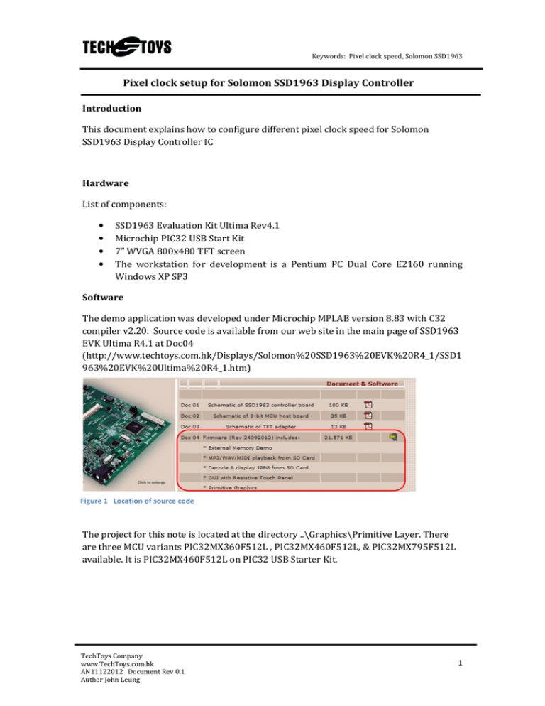
Pixel clock setup for Solomon SSD1963 Display Controller
advertisement

Keywords: Pixel clock speed, Solomon SSD1963 Pixel clock setup for Solomon SSD1963 Display Controller Introduction This document explains how to configure different pixel clock speed for Solomon SSD1963 Display Controller IC Hardware List of components: • • • • SSD1963 Evaluation Kit Ultima Rev4.1 Microchip PIC32 USB Start Kit 7” WVGA 800x480 TFT screen The workstation for development is a Pentium PC Dual Core E2160 running Windows XP SP3 Software The demo application was developed under Microchip MPLAB version 8.83 with C32 compiler v2.20. Source code is available from our web site in the main page of SSD1963 EVK Ultima R4.1 at Doc04 (http://www.techtoys.com.hk/Displays/Solomon%20SSD1963%20EVK%20R4_1/SSD1 963%20EVK%20Ultima%20R4_1.htm) Figure 1 Location of source code The project for this note is located at the directory ..\Graphics\Primitive Layer. There are three MCU variants PIC32MX360F512L , PIC32MX460F512L, & PIC32MX795F512L available. It is PIC32MX460F512L on PIC32 USB Starter Kit. TechToys Company www.TechToys.com.hk AN11122012 Document Rev 0.1 Author John Leung 1 Keywords: Pixel clock speed, Solomon SSD1963 The options as shown in Figure 2(HardwareProfile.h)were chosen for our particular hardware combination. Figure 2 Options in HardwareProfile.h From the project workspace, open the file SSD1963.c. Browse to ResetDevice(void). 1. It is important to notice that, before the SSD1963 is configured to run at any higher speed, it is running at 10MHz which is exactly the crystal frequency in hardware. Therefore, it is not possible to write to SSD1963 at any speed higher than 10MHz before the PLL is locked. That’s why the function WriteDataSlow() is used to match the speed of 10MHz. Figure 3 shows an extract from the source code SSD1963.c. TechToys Company www.TechToys.com.hk AN11122012 Document Rev 0.1 Author John Leung 2 Keywords: Pixel clock speed, Solomon SSD1963 Figure 3 An extract from SSD1963.c in ResetDevice(void) After PLL has been locked at 120MHz, we may use a higher writing speed. For Microchip PIC32, it is possible to set PMP waiting periods at the lowest values. OK, now we have a SSD1963 running at 120MHz. The pixel clock is divided from the master clock with divisors at register LCDC_FPR. Down the function ResetDevice(void) you may see the configuration for 5” or 7” TFT panels as below (Figure 4). Figure 4 Register LCDC_FPR for PCLK speed TechToys Company www.TechToys.com.hk AN11122012 Document Rev 0.1 Author John Leung 3 Keywords: Pixel clock speed, Solomon SSD1963 The equation to obtain LCDC_FPR is: PCLK = Master Clock * (LCDC_FPR+1)/2^20. If we need a PCLK at 40MHz, the value of LCDC_FPR is calculated as: LCDC_FPR = 2^20*40/120 – 1 = 349524 (0x55554). Similar, the value of LCDC_FPR for PCLK@30MHz = 2^20*30/120 – 1 = 262143 (0x3FFFF) Figures below show the waveform of PCLK output from SSD1963. WriteCommand(CMD_SET_PCLK); CS_LAT_BIT = 0; WriteData(0x05); WriteData(0x55); WriteData(0x54); CS_LAT_BIT = 1; Figure 5 Set LCDC_FPR a value of 0x55554 for PCLK at 40MHz WriteCommand(CMD_SET_PCLK); CS_LAT_BIT = 0; WriteData(0x03); WriteData(0xFF); WriteData(0xFF); CS_LAT_BIT = 1; Figure 6 Set LCDC_FPR a value of 0x3FFFF for PCLK at 30MHz TechToys Company www.TechToys.com.hk AN11122012 Document Rev 0.1 Author John Leung 4 Keywords: Pixel clock speed, Solomon SSD1963 This page is empty TechToys Company www.TechToys.com.hk AN11122012 Document Rev 0.1 Author John Leung 5


