Back Plate Installation (Horizontal) Revel Wall (Compact Fluorescent)

Installation Instructions for
Revel Wall (Compact Fluorescent)
700WSRVL_-CF
920WSREVELCF
1.1
W ALL C OLLECTION
G P I :
This product is suitable for damp locations.
This product can mount to either a 4" square electrical box with round plaster ring or an octagon electrical box.
NOTE: If mounting vertically, skip to section 3.
C AUTION — RISK OF FIRE
This product requires installation by a qualified electrician. Before installing be sure to read all instructions and DISCONNECT POWER TO THE
ELECTRICAL BOX.
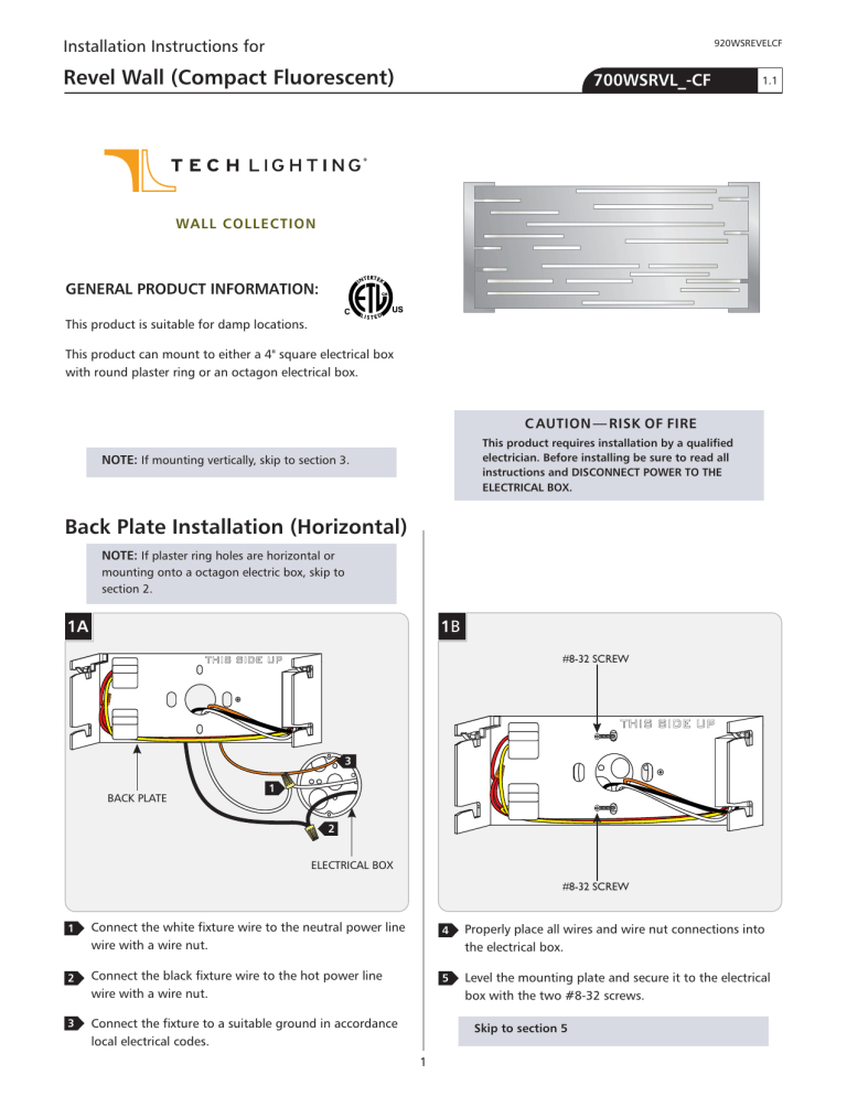
Back Plate Installation (Horizontal)
NOTE: If plaster ring holes are horizontal or mounting onto a octagon electric box, skip to section 2.
1A
THIS SIDE UP
1
B
#8-32 SCREW
THIS SIDE UP
3
1
BACK PLATE
2
ELECTRICAL BOX
#8-32 SCREW
1 Connect the white fixture wire to the neutral power line wire with a wire nut.
2
Connect the black fixture wire to the hot power line wire with a wire nut.
3 Connect the fixture to a suitable ground in accordance local electrical codes.
1
4 Properly place all wires and wire nut connections into the electrical box.
5 Level the mounting plate and secure it to the electrical box with the two #8-32 screws.
Skip to section 5
Back Plate Installation (Horizontal)
2A
THUMB NUT
MOUNTING PLATE
2C
THIS SIDE UP
THUMB NUT
1 Unscrew and remove the two thumb nuts from the mounting plate.
2B
MOUNTING STUD
CROSSBAR
#8-32 SCREW
MOUNTING STUD
#8-32 SCREW
ELECTRICAL BOX
2 Align the two mounting studs vertically and mount the crossbar to the electrical box with the two #8-32 screws provided.
5
3
4
3 Connect the white fixture wire to the neutral power line wire with a wire nut.
4
Connect the black fixture wire to the hot power line wire with a wire nut.
5 Connect the fixture to a suitable ground in accordance local electrical codes.
2D
THUMB NUTS
THIS SIDE UP
THUMB NUTS
5 Properly place all wires and wire nut connections into the electrical box.
6 Place the back plate onto the mounting plate and secure it tightly by reinstalling the thumb nuts.
Skip to section 5
2
Back Plate Installation (Vertical)
NOTE: If plaster ring holes are vertical or mounting onto a octagon electric box, skip to section 4.
3A
Back Plate Installation (Vertical)
4A
THUMB NUT
MOUNTING PLATE
THUMB NUT
BACK PLATE
3
1
2
ELECTRICAL BOX
1 Connect the white fixture wire to the neutral power line wire with a wire nut.
2
Connect the black fixture wire to the hot power line wire with a wire nut.
3 Connect the fixture to a suitable ground in accordance local electrical codes.
3B
1 Unscrew and remove the two thumb nuts from the mounting plate.
4B
#8-32 SCREW
MOUNTING STUD
MOUNTING STUD
#8-32 SCREW ELECTRICAL BOX
#8-32 SCREW
2 Align the two mounting studs horizontally and mount the crossbar to the electrical box with the two #8-32 screws provided.
#8-32 SCREW
4 Properly place all wires and wire nut connections into the electrical box.
5 Level the mounting plate and secure it to the electrical box with the two #8-32 screws.
Skip to section 5
3
4C
Install the Lamp and Shade Assembly
5A
SOCKET LAMP
THIS SIDE UP
5
3
4
MAX 13 Watt 2GX7 Base Twin
Tube Compact Fluorescent Lamp.
1 Push the lamp base into the socket.
3 Connect the white fixture wire to the neutral power line wire with a wire nut.
4
Connect the black fixture wire to the hot power line wire with a wire nut.
5 Connect the fixture to a suitable ground in accordance local electrical codes.
4D
5B
KEYED
SLOTS
STUDS
THUMB NUTS THUMB NUTS
2 Line up the studs on the shade assembly to the keyed slots on the back plate.
3 Slide the assembly onto the back plate and follow the keyed slot until it is firmly in place.
SAVE THESE INSTRUCTIONS!
6 Properly place all wires and wire nut connections into the electrical box.
7 Place the back plate onto the mounting plate and secure it tightly by reinstalling the thumb nuts.
4
7400 Linder Ave, Skokie, IL 60077
847.410.4400
www.techlighting.com
© 2012 Tech Lighting, L.L.C. All rights reserved. The "Tech Lighting" graphic is a registered trademark of Tech Lighting, L.L.C. Tech Lighting reserves the right to change specifications for product improvements without notification.
A Generation Brands Company


