department of ice
advertisement
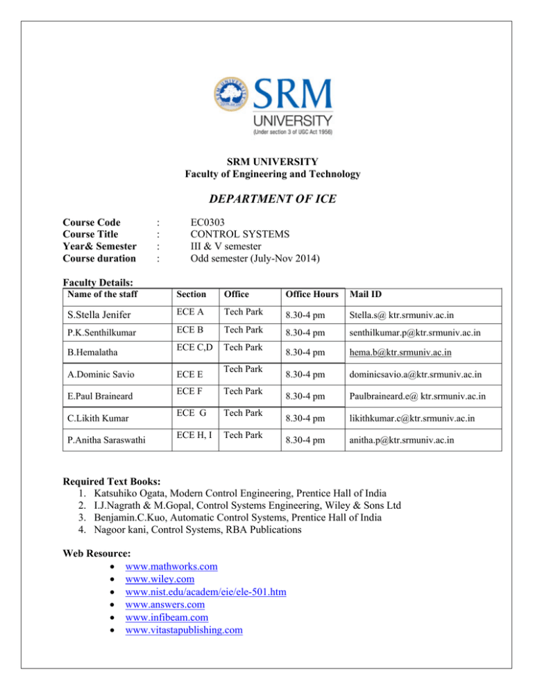
SRM UNIVERSITY Faculty of Engineering and Technology DEPARTMENT OF ICE Course Code Course Title Year& Semester Course duration : : : : EC0303 CONTROL SYSTEMS III & V semester Odd semester (July-Nov 2014) Faculty Details: Name of the staff Section Office Office Hours Mail ID S.Stella Jenifer ECE A Tech Park 8.30-4 pm Stella.s@ ktr.srmuniv.ac.in P.K.Senthilkumar ECE B Tech Park 8.30-4 pm senthilkumar.p@ktr.srmuniv.ac.in ECE C,D Tech Park 8.30-4 pm hema.b@ktr.srmuniv.ac.in 8.30-4 pm dominicsavio.a@ktr.srmuniv.ac.in 8.30-4 pm Paulbraineard.e@ ktr.srmuniv.ac.in 8.30-4 pm likithkumar.c@ktr.srmuniv.ac.in 8.30-4 pm anitha.p@ktr.srmuniv.ac.in B.Hemalatha A.Dominic Savio E.Paul Braineard C.Likith Kumar P.Anitha Saraswathi ECE E Tech Park ECE F Tech Park ECE G Tech Park ECE H, I Tech Park Required Text Books: 1. Katsuhiko Ogata, Modern Control Engineering, Prentice Hall of India 2. I.J.Nagrath & M.Gopal, Control Systems Engineering, Wiley & Sons Ltd 3. Benjamin.C.Kuo, Automatic Control Systems, Prentice Hall of India 4. Nagoor kani, Control Systems, RBA Publications Web Resource: • www.mathworks.com • www.wiley.com • www.nist.edu/academ/eie/ele-501.htm • www.answers.com • www.infibeam.com • www.vitastapublishing.com Prerequisite : Electric circuits & Networks Objective: 1. 2. 3. 4. 5. To Understand the fundamentals of mathematical modeling To derive transfer function of control system components To analyze the transient and steady state response of first and second order systems To analyze the stability of systems from transfer function forms To understand the frequency domain tools for analysis and design of linear control systems \ Tentative test details and portions: Cycle Test - I: 01.08.14 Cycle Test –II: 15.08.14 Model Exam: 20.10.14 Unit I Unit III All five units Assessment details Cycle test I Cycle test II Model test Surprise test (3* 5 Points) Attendance TOTAL 10 points 10 points 20 points 05 points 05 points 50 Points Outcomes Students who have successfully completed this course Course outcome Program outcome Mathematical modeling of linear control systems • Transfer function of control system components • Transient and steady state response of first and second order systems • Stability analysis of systems from transfer function • Frequency domain analysis A: The student will be able to obtain the mathematical model of mechanical and electrical systems. B: The student will have a broad knowledge in developing the transfer function of potentiometers, tachogenerators, motor, gear trains & controllers C. Student will be able analyze transient and steady state response of system for step, ramp and impulse inputs D. Student will be able analyze the stability of higher order systems using routh array. E. Student will be able to determine the frequency domain specification from various plots like Bode, nyquist, Polar and M&N circles • Detailed Session Plan Day DAY 1 DAY 2 DAY 3 DAY 4 DAY 5 DAY 6 DAY 7 DAY 8 DAY 9 DAY 10 DAY 11 DAY 12 DAY 13 DAY 14 DAY 15 DAY 16 DAY 17 DAY 18 DAY 19 DAY 20 DAY 21 DAY 22 DAY 23 DAY 24 DAY 25 DAY 26 DAY 27 DAY 28 DAY 29 DAY 30 Name of the topics Reference UNIT-I: Introduction and classification of control systems Nagrath & Gopal Linear, nonlinear, time varying, time invariant, continuous, discrete, SISO and MIMO systems – definitions. Introduction to Mathematical modeling of systems Mathematical modeling of mechanical translational systems Mathematical modeling of mechanical rotational systems Mathematical modeling of electrical systems Mechanical-electrical analogies Block Diagram reduction technique Signal flow graphs Surprise Test- I UNIT III: Transient and steady state response definitions Mathematical expression of standard test signals, Type & order of systems Step, ramp and impulse response of first order systems Step, ramp and impulse response of second order systems Step response of second order critically damped systems Step response of second order Over damped systems Time domain specifications of second order under damped systems Steady state error analysis Related problems UNIT IV: Stability analysis & characteristic equation Location of roots in S-plane for stability Routh’s stability criterion Relative stability analysis Root locus technique Construction of root loci for negative feed back systems Related Problems Surprise Test -III UNIT V: Frequency response analysis Frequency domain specifications of second order systems Bode plots and stability (gain and phase) margins Nagrath & Gopal Nagrath & Gopal Nagrath & Gopal Nagrath & Gopal Nagrath & Gopal Nagrath & Gopal Nagrath & Gopal Nagrath & Gopal Nagoor kani(chapter 3) Nagoor kani Nagoor kani Nagoor kani Nagoor kani Nagoor kani Nagoor kani Nagoor kani Benjamin.C.Kuo Benjamin.C.Kuo Benjamin.C.Kuo Benjamin.C.Kuo Benjamin.C.Kuo Benjamin.C.Kuo Katsuhiko ogata(chapter 8) Katsuhiko ogata Katsuhiko ogata DAY 31 DAY 32 DAY 33 DAY 34 DAY 35 DAY 36 DAY 37 DAY 38 DAY 39 DAY 40 DAY 41 DAY 42 DAY 43 DAY 44 DAY 45 Need for compensation -Introduction to lead, lag, lead-lag compensating networks Minimum phase& non-minimum phase systems Construction of Polar plots Construction of constant M and N circles Construction of Nichols chart Construction of Nyquist stability criterion Discussion of 2 marks UNIT II: Transfer function of potentiometers Transfer function of armature controlled DC motor Transfer function of field controlled DC motor Transfer function of tachogenerators Transfer function of gear trains Transfer function of P,PI,PD controller Transfer function of PID controller Surprise Test-II Katsuhiko ogata Katsuhiko ogata Katsuhiko ogata Katsuhiko ogata Katsuhiko ogata Katsuhiko ogata Nagrath & Gopal Nagrath & Gopal Nagrath & Gopal Nagrath & Gopal Nagrath & Gopal Nagrath & Gopal Nagrath & Gopal
