D700C120UVT-Vx - Universal Lighting Technologies
advertisement
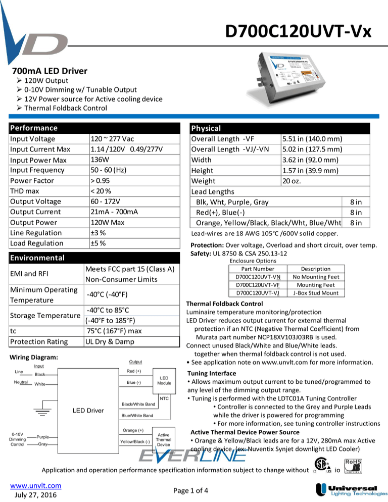
D700C120UVT-Vx 700mA LED Driver 120W Output 0-10V Dimming w/ Tunable Output 12V Power source for Active cooling device Thermal Foldback Control Performance Physical Input Voltage Input Current Max Input Power Max Input Frequency Power Factor THD max Output Voltage Output Current Output Power Line Regulation Load Regulation 120 ~ 277 Vac 1.14 /120V 0.49/277V 136W 50 - 60 (Hz) > 0.95 < 20 % 60 - 172V 21mA - 700mA 120W Max ±3 % ±5 % Overall Length -VF 5.51 in (140.0 mm) Overall Length -VJ/-VN 5.02 in (127.5 mm) Width 3.62 in (92.0 mm) Height 1.57 in (39.9 mm) Weight 20 oz. Lead Lengths Blk, Wht, Purple, Gray 8 in Red(+), Blue(-) 8 in Orange, Yellow/Black, Black/Wht, Blue/Wht 8 in Lead-wires are 18 AWG 105°C /600V solid copper. Protection: Over voltage, Overload and short circuit, over temp. Safety: UL 8750 & CSA 250.13-12 Environmental EMI and RFI Meets FCC part 15 (Class A) Non-Consumer Limits Minimum Operating Temperature -40°C (-40°F) Output Input Line Neutral Red (+) Black Blue (-) White LED Module NTC Black/White Band LED Driver Blue/White Band Orange (+) 0-10V Dimming Control Purple Gray Yellow/Black (-) Description No Mounting Feet Mounting Feet J-Box Stud Mount Thermal Foldback Control Luminaire temperature monitoring/protection LED Driver reduces output current for external thermal protection if an NTC (Negative Thermal Coefficient) from Murata part number NCP18XV103J03RB is used. Connect unused Black/White and Blue/White leads. together when thermal foldback control is not used. • See application note on www.unvlt.com for more information. -40°C to 85°C Storage Temperature (-40°F to 185°F) tc 75°C (167°F) max Protection Rating UL Dry & Damp Wiring Diagram: Enclosure Options Part Number D700C120UVT-VN D700C120UVT-VF D700C120UVT-VJ Active Thermal Device Tuning Interface • Allows maximum output current to be tuned/programmed to any level of the dimming output range. • Tuning is performed with the LDTC01A Tuning Controller • Controller is connected to the Grey and Purple Leads while the driver is powered for programming • For more information, see tuning controller instructions Active Thermal Device Power Source • Orange & Yellow/Black leads are for a 12V, 280mA max Active cooling device (ex: Nuventix Synjet downlight LED Cooler) Application and operation performance specification information subject to change without notification. www.unvlt.com July 27, 2016 Page 1 of 4 D700C120UVT-Vx Programmable Tuned Output Settings • • This Everline LED Driver can be configured to set its current output to a selected fraction of their maximum rated design level. This function is called tuning (or also high-end trim) and it can be implemented with the LDTC01A using the Selector rotary switches. Tuning assignments are stored in driver memory and are not lost when power is removed. All factory produced drivers are tuned to maximum output unless otherwise noted on the label. Tuning SET Levels are listed in the table to the right. The SET Level corresponds to an associated Output Current value. Refer to application note EVD06 at www.unvlt.com for additional information. 0-10V Analog Dimming Interface Analog 0 to 10 vDC Voltage Control -Use Violet (+) & Gray (-) for connection to 0-10vDC. - 10v = maximum output, 0v = minimum output - Driver protected if line voltage is applied. - Wiring Violet & Gray together provides min. light output. -Capping Violet & Gray separately provides 100% light output. - 0-10V interface can be wired as Class 1 or Class 2 Circuit. • Driver will source a maximum of 250uA for control needs. Output Current (A) SET Value Output Current (A) SET Value Output Current (A) 100 0.700 80 0.534 60 0.384 99 0.690 79 0.526 59 0.376 98 0.681 78 0.518 58 0.369 97 0.673 77 0.510 57 0.362 96 0.665 76 0.503 56 0.355 95 0.656 75 0.495 55 0.348 94 0.648 74 0.487 54 0.341 93 0.639 73 0.480 53 0.334 92 0.631 72 0.472 52 0.327 91 0.623 71 0.465 51 0.321 90 0.614 70 0.457 50 0.314 89 0.606 69 0.449 49 0.307 88 0.598 68 0.442 48 0.300 87 0.590 67 0.435 47 0.293 86 0.582 66 0.427 46 0.287 85 0.574 65 0.420 45 0.280 84 0.566 64 0.413 44 0.274 83 0.558 63 0.405 43 0.267 82 0.550 62 0.398 42 0.260 81 0.542 61 0.391 41 0.254 40 0.247 Output Current Dimming Curve 0.8 0.7 Output Current (A) • SET Value 0.6 0.5 0.4 0.3 0.2 0.1 0 0 1 2 3 4 5 6 7 8 9 0-10V Control Voltage Application and operation performance specification information subject to change without notification. www.unvlt.com July 27, 2016 Page 2 of 4 10 D700C120UVT-Vx Performance: Efficiency, THD, & Power Factor Typical performance measurements are shown. The charts are to be used as a guideline and not for specification use. Output power based on maximum rated output current and varying load voltages. Application and operation performance specification information subject to change without notification. www.unvlt.com July 27, 2016 Page 3 of 4 D700C120UVT-Vx Tc Location For the “N” and “F” versions, Tc location is on the bottom of the case. For the “J” version with the leads exiting out the bottom, the screw on the side of the case is oriented to the right and the Tc is located on the side with the label. -VF Case Conditions of Acceptability – 1. 2. 1. 2. 3. 4. 5. 6. 7. 8. -VJ Case 2.72” These products are for use only in (or with) complete end product 1.45” equipment where the acceptability of the combination is determined by CSA International or others having jurisdiction. The product shall be installed in compliance with the enclosure, mounting, mounting surface, strain relief, pushback relief, spacing, segregation, and all other applicable requirements of the End Product in which it is employed. Suitability shall be determined during End Product Certification Evaluation. . Product / product installation into end product is subject to any additional applicable requirement(s) of all applicable end product standard(s). These requirements shall be verified during end product evaluation. These Drivers were evaluated for use in an elevated ambient not exceeding 41°C and the maximum case temperature at (Tc) location should not exceed 75°C when the driver is installed in the end-use application. These products are suitable for use in wet locations only when the optional CSA/UR (cUS, INT) water resistant wiring is incorporated in the products. Otherwise the products are suitable for damp locations only. The output from the 0-10 Vdc dimming interface (violet and gray leads) was tested and found compliant with the Class 2 limits in accordance with UL 1310 and CSA C22.2 No. 223. The Mechanical Strength test on enclosures was performed in accordance with UL 8750 and CSA C22.2 No. 25013.12. The suitability of the enclosure of the unit with regards to the outcome of this test shall be determined in the end-product evaluation. All parts of these models are fully submerged in potting compound in accordance with sub-clause 41.1 (c) of UL 844 FCC Statement: This device complies with part 15 of the FCC Rules. Operation is subject to the following two conditions: (1) This device may not cause harmful interference, and (2) this device must accept any interference received, including interference that may cause undesired operation. Warranty: Universal Lighting Technologies warrants to the purchaser that each power supply will be free from defects in material or workmanship for a period of 5 years from the date of manufacture when properly installed per instructions and under normal operating conditions of use. Call 1800-225-5278 for technical assistance. Application and operation performance specification information subject to change without notification. www.unvlt.com July 27, 2016 Page 4 of 4
