RF Mixer Circuits Tutorial: Conversion Gain & Noise Figure
advertisement
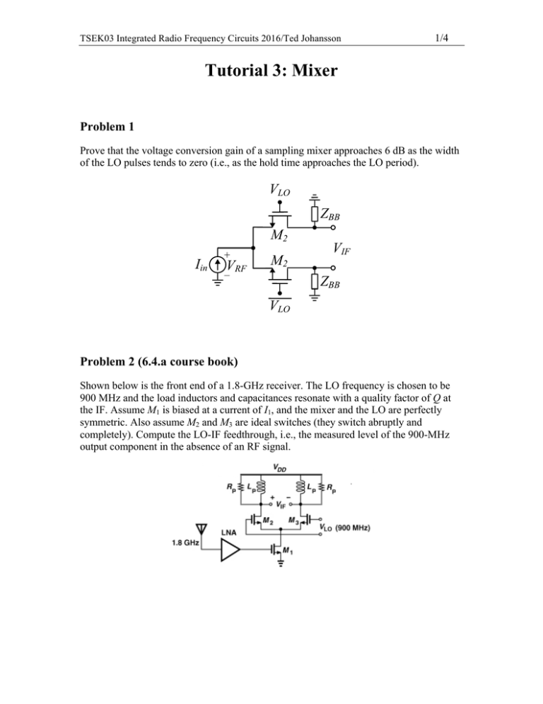
TSEK03 Integrated Radio Frequency Circuits 2016/Ted Johansson 1/4 Tutorial 3: Mixer Problem 1 Prove that the voltage conversion gain of a sampling mixer approaches 6 dB as the width of the LO pulses tends to zero (i.e., as the hold time approaches the LO period). VLO ZBB M2 Iin + VRF M2 – VIF ZBB VLO Problem 2 (6.4.a course book) Shown below is the front end of a 1.8-GHz receiver. The LO frequency is chosen to be 900 MHz and the load inductors and capacitances resonate with a quality factor of Q at the IF. Assume M1 is biased at a current of I1, and the mixer and the LO are perfectly symmetric. Also assume M2 and M3 are ideal switches (they switch abruptly and completely). Compute the LO-IF feedthrough, i.e., the measured level of the 900-MHz output component in the absence of an RF signal. TSEK03 Integrated Radio Frequency Circuits 2016/Ted Johansson 2/4 Problem 3 The circuit shown below is a dual-gate mixer used in traditional microwave design. Assume abrupt edges and a 50 % duty cycle for the LO and neglect channel-length modulation and body effect. VDD RD VRF M2 VLO M1 VIF a) Assume that M1 is an ideal switch. Determine the frequency components which appear at the mixer IF port. b) Assume when M1 is on, it has an on-resistance of Ron1. Compute the voltage conversion gain of the circuit. Assume M2 does not enter the triode region and denote its transconductance by gm2. c) Assume when M1 is is an ideal switch. Compute the voltage conversion gain of the circuit. Problem 4 Assume that in the circuit of the previous example, M1 is an ideal switch (noise contribution is zero). Derive the expression for the noise figure of the mixer. 3/4 TSEK03 Integrated Radio Frequency Circuits 2016/Ted Johansson Homework 1 Gilbert mixer and its variants are one of the most popular types of mixers used in today’s designs due to its good conversion gain, NF, linearity, and isolation. VDD R1 + VLO R2 VIF M 3 M4 M5 M 6 – + VRF M1 M2 – ISS a) Derive the expression for the conversion. b) Derive the expression to identify the frequency components at the output spectrum of the mixer IF port. c) Derive the expression for the noise figure. 4/4 TSEK03 Integrated Radio Frequency Circuits 2016/Ted Johansson Homework 2 In the circuit of Fig. 6.67 of the course book, we place a parallel RLC tank in series with the source of M4 such that at resonance, the noise contribution of M4 is reduced. Recalculate Eq. (6.116) if the tank provides an equivalent parallel resistance of Rp. (Bear in mind that Rp itself produces noise). C Rp L
