411-18305-1
Instruction Sheet
SOLARLOK Interconnection System
1.
26 JUL 2011
Rev. G
Introduction
This instruction sheet covers the installation and termination of the SOLARLOK* connectors and accessory.
2.
Supporting Documents
2.1.
Customer Drawings
Dimensions and material specifications for this product can be found in the following customer drawings
PN 1394461
PN 1394462
PN 1534226
PN 2106207
Photovoltaic Connector Pin 1 pos.
Photovoltaic Connector Socket 1 pos.
Interlock Clip
SOLARLOK Locking Collar (UL / NEC Certified)
PN 1534611, PN 1740277 T-Distributor
2.2.
Product Specification
Performance results for the SOLARLOK products can be found in Product Specification 108-18701.
2.3.
Application Specification
Connectors shall be assembled per Application Specifications 114-18488-1, to ensure correct connector
assembly and crimp quality. Please refer to SOLARLOK Application Specification 114-94061 for additional
details on contact termination.
3.
Tools
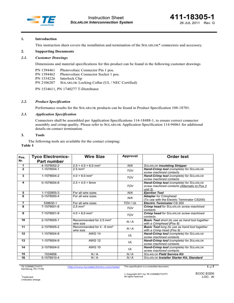
The following tools are available for the contact crimping:
Table 1
Pos.
Nr.
Tyco ElectronicsPart number
Wire Size
1
2
4-1579002-2
1-1579004-1
2.5 + 4.0 + 6.0 mm²
2.5 mm²
3
1-1579004-2
4.0 + 6.0 mm²
4
0-1579004-8
2.5 + 4.0 + 6mm
Approval
N/A
TÜV
TÜV
TÜV
5
6
1-1102855-3
0-1579000-4
For all wire sizes
For all wire sizes
N/A
7
8
539630-1
7-1579001-8
For all wire sizes
2,5 mm²
TÜV / UL
9
7-1579001-9
4.0 + 6,0 mm²
10
2-1579005-1
11
2-1579005-2
12
1-1579004-8
Recommended for 2.5 mm²
wire size
Recommended for 4 - 6 mm²
wire size
AWG 14
13
1-1579004-9
AWG 12
14
2-1579004-0
AWG 10
15
16
1534858
5-1579010-4
N/A
N/A
TE CONNECTIVITY,
Harrisburg, PA 17105
*
Trademark
| Indicates change
http://www.tycoelectronics.com/solar/
N/A
TÜV
TÜV
N/A
N/A
UL
UL
UL
N/A
N/A
Order text
SOLARLOK insulating Stripper
Hand-Crimp tool (complete) for SOLARLOK
screw machined contacts
Hand-Crimp tool (complete) for SOLARLOK
screw machined contacts
Hand-Crimp tool (complete) for SOLARLOK
screw machined contacts (Alternativ to Pos 2
und 3).
Ejection Tool
Adapter for Crimphead
(To use with the Electric Terminator CS200)
Electric Terminator CS 200
Crimp head for SOLARLOK screw machined
contacts
Crimp head for SOLARLOK screw machined
contacts
Basic Tool short (to use as hand tool together
with a Crimphead (Pos 8)
Basic Tool long (to use as hand tool together
with a Crimp head (Pos 9)
Hand-Crimp tool (complete) for SOLARLOK
screw machined contacts
Hand-Crimp tool (complete) for SOLARLOK
screw machined contacts
Hand-Crimp tool (complete) for SOLARLOK
screw machined contacts
SOLARLOK Field Service Kit
SOLARLOK Installer Starter Kit, Standard
This specification is a controlled document.
Copyright 2011 by TE CONNECTIVITY.
All rights reserved
1 of 7
ECOC EGD0
LOC: AI
411-18305-1
Instruction Sheet
SOLARLOK Interconnection System
4.
Accessories
4.1.
T-Distributor
26 JUL 2011
Rev. G
The T-Distributor is used for connecting a parallel circuit or coupling. Take care to ensure that the max.
overall current is not exceed. The T-Distributer must always be fully completely connected!
CAUTION: Do not disconnect the connector under load (see 5.3.4)!
Disconnect circuit from load before unplugging connectors.
Cable assemblies should be labeled using Label 1718077-1.
4.2.
Interlock Clip and SOLARLOK Locking Collar
For application of the interlock clip and the application of the SOLARLOK Locking Collar see Instruction
Sheet 408-10296
Figure 1 a:
5.
Figure1b:
Assembly Procedure for SOLARLOK Plug connector
CAUTION: This connector must be used only to interconnect firmly fixed cables.
Do not disconnect under load.
Current path must only be disconnected using approved disconnect devices.
Cable assemblies shall be labeled with PN 1718077-1.
To protect against shock, ensure that conductors and their associated connectors are separated from
opposite polarity components.
5.1.
Caution any kind of pollution (dust, humidity, etc.) during the assembly process can degrade contact and
connector performance. This applies in particular to the seals and the crimping of the contacts. A clean/dry
assembly environment is therefore essential.
5.2.
Termination of the cable wires / crimping of the contacts
The connectors accept different contacts for various wire gauges. Possible wire gauges are 2.5 mm², 4.0 mm²
and 6mm² (6mm² only Tyco Electronics Solar wire), 14 AWG, 12 AWG, and 10 AWG. The tools to be used
are selected based upon the wire gauge. For the application specification, please refer to 114-94061.
TE CONNECTIVITY,
Harrisburg, PA 17105
*
Trademark
| Indicates change
http://www.tycoelectronics.com/solar/
This specification is a controlled document.
Copyright 2011 by TE CONNECTIVITY.
All rights reserved
2 of 7
ECOC EGD0
LOC: AI
411-18305-1
Instruction Sheet
SOLARLOK Interconnection System
26 JUL 2011
Rev. G
To identify the needed contact Part Number (See the following Table 2)
Only Cables released from Tyco Electronics are permitted to use with SOLARLOK Components!
For further information, please refer to TE Application Specification 114-94061.
Table 2
Available Crimp Contacts for SOLARLOK Interconnection System
Wire Gauges
Pin Contact
Socket Contact
SOLARLOK
Crimp Tool
2.5 mm²
0-1987280-1; or *4-1105300-1
1987281-1; or *4-1105301-1
2.5 mm²
4 mm²
6.0 mm²
14 AWG
12 AWG
10 AWG
*
5.3.
*
0-1987280-2; or 5-1105300-1
*
0-1987280-4; or 7-1105300-2
*
0-1987280-1; or 4-1105300-1
*
0-1987280-2; or 5-1105300-1
*
0-1987280-4; or 7-1105300-2
*
4 mm²
*
6 mm²
*
14 AWG
*
12 AWG
*
10 AWG
1987281-2; or 5-1105301-1
1987281-3; or 7-1105301-2
1987281-1; or 4-1105301-1
1987281-2; or 5-1105301-1
1987281-3; or 7-1105301-2
) Part Number outdated
Assembling of the Connectors
The usage of any type of lubricant or oil is not allowed!
Unconnected connectors must always be protected from pollution (e.g. dust, humidity, foreign particle,
etc.).
The usage of Tyco Electronics Dust caps is recommended (refer to Application Specification 114-18488
for details).
In case of replacement of cables or components or of assembling / disassembling of the cable entry
gland, new pinch rings and seals have to be used. If a visible deformation appears at the clamping area
of the cable, the cable end needs to be trimmed to remove the deformed area.
TE CONNECTIVITY,
Harrisburg, PA 17105
*
Trademark
| Indicates change
http://www.tycoelectronics.com/solar/
This specification is a controlled document.
Copyright 2011 by TE CONNECTIVITY.
All rights reserved
3 of 7
ECOC EGD0
LOC: AI
411-18305-1
Instruction Sheet
SOLARLOK Interconnection System
5.3.1
26 JUL 2011
Rev. G
Selection of Cable Connectors
The cable connectors are delivered as Kits, containing all necessary parts including the Crimp Contacts.
There are different Cable Connector Kits available. The correct Kit selection needs to be done according to the Outside
Diameter of the cable, Wire Gauge and Polarity (See the followings Table 3)
Only Cables released from Tyco Electronics are permitted to use with SOLARLOK Components! For further
information, please refer to TE Application Specification 114-94061.
Table 3
Available Connector Kits for SOLARLOK Interconnection System
Wire Gauges
Polarity
Male
Female
Cable Diameter
Pinch Ring Style
2.5 mm²
+
0-1394461-1
0-1394462-1
1987056-1
2.5 mm²
-
0-1394461-2
0-1394462-2
Cable Diameter
(Outside)
2.5 mm²
N
6-1394461-1
-
4.0 mm²
+
0-1394461-3
0-1394462-3
4.0 mm²
-
0-1394461-4
0-1394462-4
4.0 mm²
N
6-1394461-2
-
6.0 mm²
+
6-1394461-5
5-1394462-5
6.0 mm²
-
6-1394461-6
5-1394462-6
6.0 mm²
N
6-1394461-4
-
2.5 mm²
+
0-1394461-7
4-1394462-6
2.5 mm²
-
0-1394461-8
4-1394462-7
2.5 mm²
N
6-1394461-3
-
4.0 mm²
+
7-1394461-0
4-1394462-8
4.0 mm²
-
7-1394461-1
4-1394462-9
4.0 mm²
N
7-1394461-2
-
from 5.5mm
up to 7.8mm
Cable Diameter
(Outside)
1740379-2
from 4.5mm
up to 5.5mm
When assembling the connectors, the following sequence must be followed:
5.3.2
Stripping the Wire (see Application Spec. 114-94061 (see Fig. 3)
9mm ±1mm
Figure 3
5.3.2.1 Insert the stripped wire into the wire crimp barrel until it stops. While holding the wire in place,
squeeze tool handles together until ratchet releases (see Fig. 4)
Figure 4
TE CONNECTIVITY,
Harrisburg, PA 17105
*
Trademark
| Indicates change
http://www.tycoelectronics.com/solar/
This specification is a controlled document.
Copyright 2011 by TE CONNECTIVITY.
All rights reserved
4 of 7
ECOC EGD0
LOC: AI
411-18305-1
Instruction Sheet
SOLARLOK Interconnection System
26 JUL 2011
Rev. G
For further information, please refer to TE Application Specification 114-94061.
Make sure that the contact is correctly positioned in the applicator or hand tool. For easier handling, use the
locator.
For pre-assembled connectors, start with chapter 5.3.2.4
5.3.2.2 Press seal into the connector housing until it stops (see Fig. 5 and 6).
Figure 5 Components of connector housing
Figure 6 Pre assembled seal
5.3.2.3 Screw backshell nut onto connector housing (2 to 3 turns max. see Fig. 7)
Figure 7 Assembled Connector Housing
5.3.2.4 Push contact with cable into the connector housing until you hear the contact click into plastic housing;
pull back slightly to ensure the contact is locked (Figure 8)
Figure 8 Contact assembly
5.3.2.5 Screw backshell nut with a torque wrench with slotted insert (TE-PN: 523229-1) onto the connector
housing. Tighten backshell nut to an initial torque of max. 1.3+0.2 Nm (see Fig. 9 and 10)
Figure 9
Tighten back shell nut to a initial torque of max. 1.3+0.2 Nm
TE CONNECTIVITY,
Harrisburg, PA 17105
*
Trademark
| Indicates change
http://www.tycoelectronics.com/solar/
Figure 10
Label female connector with label
“Do not disconnect under load”.
This specification is a controlled document.
Copyright 2011 by TE CONNECTIVITY.
All rights reserved
5 of 7
ECOC EGD0
LOC: AI
411-18305-1
Instruction Sheet
SOLARLOK Interconnection System
5.3.3
26 JUL 2011
Rev. G
Connector Mating
When mating the SOLARLOK connectors, ensure the following:
Connectors labeled with a + or – are keyed and can only be mated to similarly marked and keyed connectors.
Caution: The “neutral” designated pin-connectors incorporate no keying features and may
be freely mated to either + or – keyed female connectors. The neutral product must not be
used where maintaining polarity is critical. It is only admitted for serial connections.
At Solarlock interconnection System the usage of the “neutral” designed pin connector is
only necessary for the Junction box termination
The polarity of the "neutral" connector must be labeled with PN 1718078-1 or -2 nearby the connector.
When mating the connector, the following must always be followed:
The plus- and minus-coded connectors can only be mated to a similarly coded connector (see Fig. 10).
The connector is fully latched only when the latches are flush with the mating connector.
Figure 11 (Female connector)
5.3.4
Disconnecting
CAUTION: Unplugging Under Load Not Permitted: PV plug connections must not be un-plugged
while under load. They can be placed in an unloaded state e.g. by switching off the DC/AC converter
or breaking the AC circuit. Plugging and unplugging while under tension is not permitted.
Cable assemblies must be labeled using Label PN 0-1718077-1. Unmating of the connector:
Figure 12
1.
The locking mechanism is opened by depressing the latches as shown in Figure 11.
2.
While depressing the latches, disconnect the connector by pulling the connectors halves apart.
TE CONNECTIVITY,
Harrisburg, PA 17105
*
Trademark
| Indicates change
http://www.tycoelectronics.com/solar/
This specification is a controlled document.
Copyright 2011 by TE CONNECTIVITY.
All rights reserved
6 of 7
ECOC EGD0
LOC: AI
411-18305-1
Instruction Sheet
SOLARLOK Interconnection System
5.3.5
26 JUL 2011
Rev. G
Cable Routing
A minimum bending radius R ≥ 5 x cable diameter must be maintained.
The cable must be routed in a way that the tensile stress on the conductor or connections is prevented.
6.
Maximum operating conditions
max. system voltage: 1000V (for UL 600V)
max. current: 25A at 85°C
operating temperature: -40°C up to 115°C
Ambient temperature (per IEC 85°C / per UL 75°C) plus temperature rise caused by current
TE CONNECTIVITY,
Harrisburg, PA 17105
*
Trademark
| Indicates change
http://www.tycoelectronics.com/solar/
This specification is a controlled document.
Copyright 2011 by TE CONNECTIVITY.
All rights reserved
7 of 7
ECOC EGD0
LOC: AI


