Document
advertisement

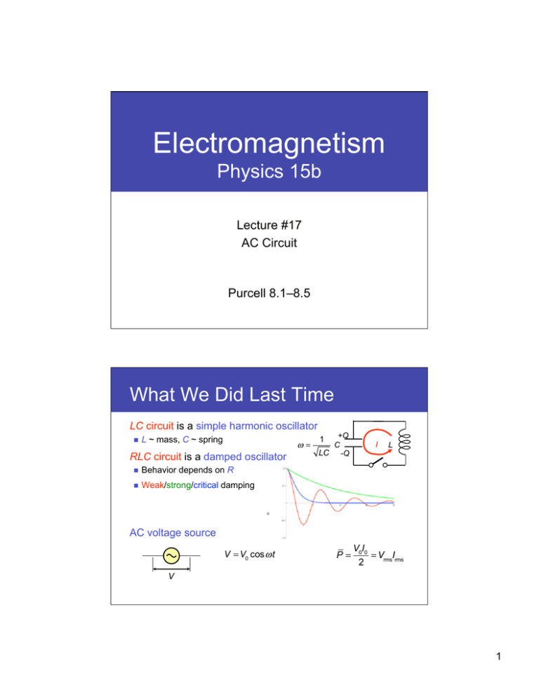
Electromagnetism Physics 15b Lecture #17 AC Circuit Purcell 8.1–8.5 What We Did Last Time LC circuit is a simple harmonic oscillator L ~ mass, C ~ spring ω= RLC circuit is a damped oscillator Behavior depends on R Weak/strong/critical damping +Q C LC -Q 1 I L 0 AC voltage source V = V0 cos ω t P= V0I0 = VrmsIrms 2 V 1 Today’s Goals Introduce Impedance Extension of resistance into AC circuits R, L, and C (and combinations) can be treated together Catch: must do this in complex numbers Use impedance to analyze simple AC circuits 1. Frequency filters Combine R, L, or C to selectively remove (= filter out) signals with high or low frequencies 2. Resonance circuit Combine R + L + C to enhance signals near a particular frequency Quality Factor Q Impedance Impedance is a generalization of resistance Drive “something” with an AC voltage source Could be an R, C, L or a combination Z I(t) How does the current relate to the voltage? For R, the answer is simple: V0 cos ω t = R ⋅ I0 cos ω t V0 = R ⋅ I0 V(t) It would be nice if L and C were as simple as V0 = Z ⋅ I0 Not possible as long as we keep using cosωt and sinωt To simplify, we introduce a complex notation V(t) = Re(V0e iω t ) = V0 cos ω t V(t) Omit “Re” as implicitly being there 2 Impedance of C Q(t) = CV(t) = CV0e iω t Let’s study C first +Q C I(t) = −Q I dQ(t) = CV0 iω e iω t dt The (complex) current can be written as I(t) = I0e iω t where I0 = iω CV0 V If we take the real part I(t) = −CV0ω sin ω t Define the impedance of a capacitor by Z(ω ) = V0 I0 = 1 iω C V0 = Z ⋅ I0 This is a frequency-dependent imaginary number Impedance of L For an L connected to the same source L V(t) = V0e iω t = L I V dI(t) dt V0 V e iω t dt = 0 e iω t ∫ L iω L V0 Therefore I = 0 iω L V0 Take the real part I(t) = sin ω t Lω I(t) = The impedance of an inductor is V Another frequency-dependent Z = 0 = iω L imaginary number I0 3 Magnitude of Impedance Impedance of L and C depends on the frequency Z V0 = Z(ω )I0 I |Z | V Z L = iω L ZR = R ZC = ω Impedance varies depending on the frequency ω 1 iω C Phase of Impedance Capacitor C I(t) = Re(iω CV0e iω t ) ⎛ V0 iω t ⎞ e ⎟ ⎝ iω L ⎠ Inductor L I(t) = Re ⎜ = = −ω CV0 sin ω t Voltage lags the current by 90º V(t) V0 sin ω t ωL Voltage leads the current by 90º I(t) V(t) I(t) Both amplitudes and phases are expressed in the impedance Z 1 π π ZC = → arg(ZC ) = − ZL = iω L → arg(ZL ) = iω C 2 2 4 Combining Impedance Total impedance of a network of resistors, capacitors, and inductors can be calculated by adding up ZR, ZC, and ZL Same rules as resistor addition — just in complex numbers R C L Z= Z = R + iω L 1 R 1 R = + iω C 1+ iω RC R Impedance summarizes the network’s AC characteristics iω t V V(t) V0e Z= = = 0 iω t I(t) I0e I0 Magnitude |Z| is the ratio between peak voltage and peak current Complex phase arg(Z) is the phase difference between voltage and current Low Pass Filter Series R + C is driven by an AC voltage source 1 Total impedance is ZRC = R + iω C Current is V0e iω t V0 I(t) = = e iω t ZRC R + 1 iω C R Vin = V0eiωt C Vout The “output” voltage around C is Vout (t) = ZCI(t) = V0 V0 1 e iω t = e iω t iω C R + 1 iω C iω RC + 1 At low frequency (ωRC << 1), Vout is close to Vin At high frequency (ωRC >> 1), Vout approaches zero This network passes low freq. and blocks high freq. = a low-pass filter 5 Low Pass Filter The frequency response of a simple low-pass filter is Vout Vin = 1 1 = iω RC + 1 (ω RC)2 + 1 In log-log plot, it’s two straight lines joined by a round corner The cut-off frequency is ω= 1 RC 1 2π RC = 12 Vin f= This is where Vout 1 0.1 0.01 0.001 0.01 0.1 1 10 100 ω RC Above the cut-off, Vout drops inversely proportionally to ω Such filter is called a first-order filter EE people call it a “−6 dB/octave” or “−20 dB/decade” filter Other Filters Low-pass and high-pass filters can be built with RC or RL RC low-pass CR high-pass ω cutoff = 1 RC LR low-pass RL high-pass ω cutoff = R L All are first-order, ±6 dB/octave filters Steeper filters are usually made with active electronics Nowadays often with digital signal processing 6 Series RLC Circuit An AC voltage source drives R + L + C iω t Current is common I = I e R 0 L C VC VL Total voltage is V = V0e iω t = VR +VL +VC VR Use impedance ⎛ 1 ⎞ iω t V0e iω t = ⎜ R + iω L + Ie iω C ⎟⎠ 0 ⎝ Im iωL Total impedance Ztotal Remember: addition of impedance works in the same way as resistance It just has to be done in the complex plane 1/iωC Re R Resonance Im Total impedance changes with ω ZL = iωL grows, ZC = 1/iωC shrinks Magnitude is Ztotal ⎛ 1 1 ⎞ = R + iω L + = R2 + ⎜ωL − iω C ω C ⎟⎠ ⎝ iωL Ztotal 2 R Re i/iωC Minimum when ZL and ZC cancel each other min Ztotal = R when iω L + 1 =0 iω C ω0 = 1 Resonance LC frequency At the resonance Impedance is minimum Current is maximum Impedance is real Current and voltage are in phase 7 Resonance Im At the resonance Impedance is minimum Current is maximum Impedance is real Current and voltage are in phase iωL Ztotal R Re 1/iωC R = 2.5Ω L = 5 µH C = 2 nF 5Ω I0 1 1 = = V0 Z R 2 + ω L − ω1C ( 10Ω ) 2 Current peaks at the resonance 9 8 10 11x106 rad/s Peak is higher and narrower for smaller R Phase Phase of impedance tells us if V and I are synchronized ⎛ ω L − ω1C ⎞ arg Z = arctan ⎜ ⎟ ⎝ R ⎠ Im iωL Ztotal ( ) It changes from –90º to +90º as ω crosses the resonance R = 2.5Ω 9 Re 1/iωC Current leads voltage below the resonance 5Ω 8 R 10Ω 10 11x106 rad/s L = 5 µH C = 2 nF Current lags behind voltage above the resonance Phase shift is more abrupt for smaller R 8 Quality Factor How steep (or narrow) is the resonance? Look at the frequencies where Im(Z) and Re(Z) are the same size That’s where I0 is 1/√2 times the peak value ωL − ω2 = 1 R2 R2 R4 + 2± 3 + 4 LC 2L L C 4L Suppose the damping is weak, i.e., R 2 L C ω2 ≈ 1 =R ωC 1 R ± LC L 1 R = ω 02 ± ω 0 LC L ⎛ R ⎞ ω ≈ ω 0 ⎜ 1± 2ω 0L ⎟⎠ ⎝ Difference between the two solutions ω1 and ω2 (ω1 > ω2) is ω1 − ω 2 R 1 = ≡ Quality factor of the resonance circuit ω0 ω 0L Q The larger the Q, the narrower and steeper the resonance What is Q? Q is the relative width (in frequency) of the resonance Ex: FM stations use 87.5–108 MHz signals separated by 200 kHz The radio’s tuning circuit must have Q > Qmin = 108 × 10 6 Hz = 504 200 × 103 Hz Think of the same RLC circuit as a weak-damped oscillator − α t ± iω t The solution was Q(t) = e e R 1 R2 1 2L = α R In that time, it oscillates by The decay time is τ = ωτ ≈ ω 0 α= 2L ,ω= LC − 4L2 ≈ ω0 2L = 2Q radian R Q is (proportional to) the number of oscillations it makes before dying 9 Summary Impedance of R, C, and L ZR = VR =R IR ZC = VC IC = 1 iω C ZL = VL = iω L IL Generally a frequency-dependent complex number Low- and high-pass filters Cut-off frequency ω cutoff = 1 R or ω cutoff = RC L Resonance of an RLC circuit ω 0 = 1 LC Current amplitude peaks Phase between voltage and current changes by 180º Quality factor Q Q = ω0 = narrowness (steepness) of the resonance = how many “rings” a weakly damped oscillators make L R 10

