A Universal and Optimized Embedded System to
Control Firing Angle of Thyristors with Double-Sided
Isolation
Muhammad Usman Rafique
Department of Electrical Engineering
COMSATS Institute of Information Technology
Lahore, Pakistan
usmanrafique@ciitlahore.edu.pk
Abstract--This paper describes the implementation of a
double sided isolated, economical, easy to implement and
optimized approach to design a digital firing angle control
system for silicon controlled rectifiers (SCR) and triacs.
Currently designed circuits for this purpose use keypads to
take input from user and also use uneconomical ways to
implement zero crossing circuitry. This proposed design
eliminates the keypad and implements an economical and
cost–effective solution that helps industrial as well as home
users. The method proposed in this paper is of universal
nature and improves the design by applying the double sided
isolation and removes the pulse transformer that is not only
expensive but also provides the means of magnetic coupling
that may be harmful for the controller circuitry. The design
proposed in this paper is of universal nature that can be used
to control the home as well as industrial loads of either the
AC system running either 50 Hz or 60 Hz standard or the DC
system. In addition to that, proposed design is fully
compatible with 50 Hz and 60 Hz power systems.
change the parameters of high power AC/DC side, and
result may be fatal and unrecoverable. The method
proposed in this paper provides complete isolation
between high power load circuitry and low power control
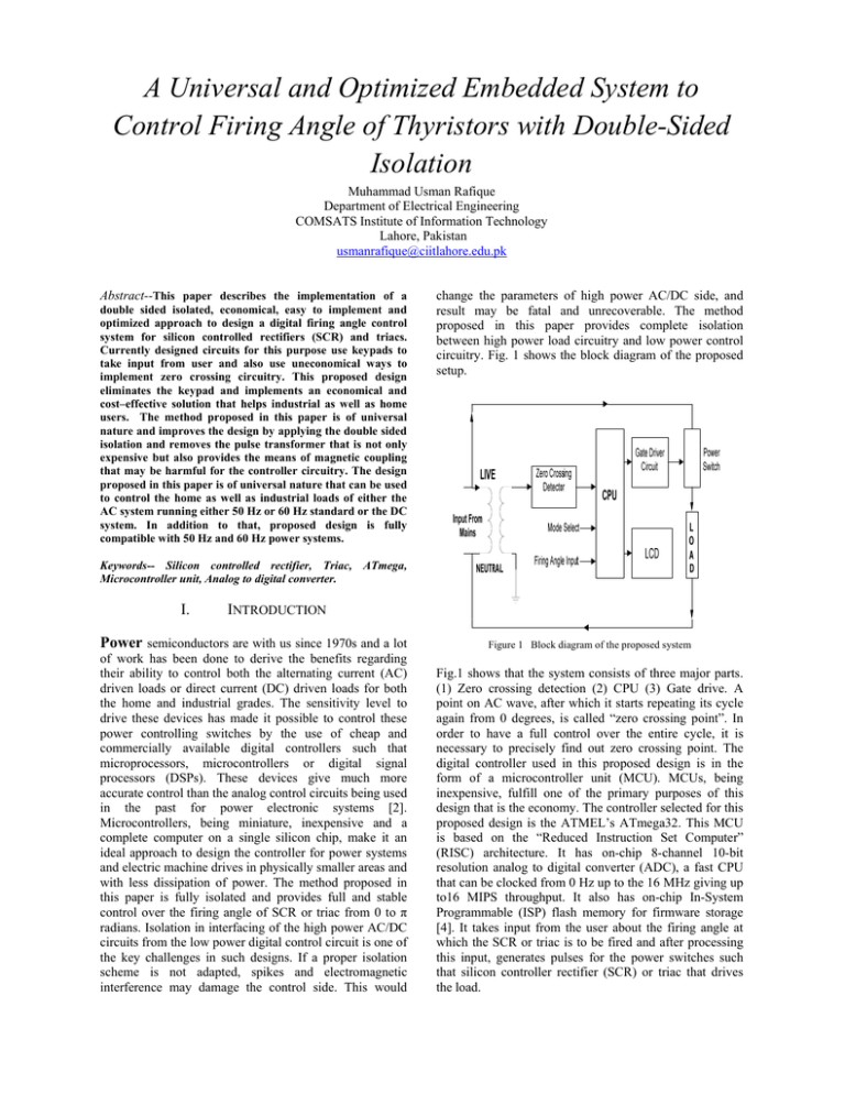
circuitry. Fig. 1 shows the block diagram of the proposed
setup.
Keywords-- Silicon controlled rectifier, Triac, ATmega,
Microcontroller unit, Analog to digital converter.
I.
INTRODUCTION
Power semiconductors are with us since 1970s and a lot
Figure 1 Block diagram of the proposed system
of work has been done to derive the benefits regarding
their ability to control both the alternating current (AC)
driven loads or direct current (DC) driven loads for both
the home and industrial grades. The sensitivity level to
drive these devices has made it possible to control these
power controlling switches by the use of cheap and
commercially available digital controllers such that
microprocessors, microcontrollers or digital signal
processors (DSPs). These devices give much more
accurate control than the analog control circuits being used
in the past for power electronic systems [2].
Microcontrollers, being miniature, inexpensive and a
complete computer on a single silicon chip, make it an
ideal approach to design the controller for power systems
and electric machine drives in physically smaller areas and
with less dissipation of power. The method proposed in
this paper is fully isolated and provides full and stable
control over the firing angle of SCR or triac from 0 to π
radians. Isolation in interfacing of the high power AC/DC
circuits from the low power digital control circuit is one of
the key challenges in such designs. If a proper isolation
scheme is not adapted, spikes and electromagnetic
interference may damage the control side. This would
Fig.1 shows that the system consists of three major parts.
(1) Zero crossing detection (2) CPU (3) Gate drive. A
point on AC wave, after which it starts repeating its cycle
again from 0 degrees, is called “zero crossing point”. In
order to have a full control over the entire cycle, it is
necessary to precisely find out zero crossing point. The
digital controller used in this proposed design is in the
form of a microcontroller unit (MCU). MCUs, being
inexpensive, fulfill one of the primary purposes of this
design that is the economy. The controller selected for this
proposed design is the ATMEL’s ATmega32. This MCU
is based on the “Reduced Instruction Set Computer”
(RISC) architecture. It has on-chip 8-channel 10-bit
resolution analog to digital converter (ADC), a fast CPU
that can be clocked from 0 Hz up to the 16 MHz giving up
to16 MIPS throughput. It also has on-chip In-System
Programmable (ISP) flash memory for firmware storage
[4]. It takes input from the user about the firing angle at
which the SCR or triac is to be fired and after processing
this input, generates pulses for the power switches such
that silicon controller rectifier (SCR) or triac that drives
the load.
Figure 2 Block diagram of ATMEL’s ATmega32 RISC Microcontroller
The firmware calculates the exact timing to generate the
triggering signals. An optocoupler isolates the MCU
circuitry from the power switch or load circuitry. The
optocoupler used in this proposed design itself has a triac
at its output stage. Input side of the optocoupler is driven
by the ATmega that drives the triac of the optocoupler.
The triac of the optocoupler, being optically isolated from
the digital controller circuitry, drives the gate of SCR or
triac in turn. Driving the gate of an SCR or of a triac
needs special care and attention. Gate current needs to be
higher than the nominated ratings of the devices to
properly trig the device and it should be supplied slightly
more than the turn on time ‘ton’ of the device. These
specifications are necessary to meet to bring the device
from blocking state to the conduction state. Gate driving
circuitry should be isolated from the control circuitry to
avoid any reverse flow of current through gate of
SCR/triac to the control circuitry or to avoid any
unwanted electromagnetic interference (EMI) resulted
from the triggering of devices other than the zero crossing
point instant. Proposed method is equally suitable for
SCR and triacs of power ratings up to the 1500 Watts
with complete isolation between gate driving circuitry and
load to be driven. This isolation problem is solved using
commonly available optotriacs and optothyristors.
II.
EXPERIMENTAL SETUP
The proposed design is implemented and fully tested
using prototype circuit boards. Heart of the system is
ATMELS’s ATmega32 microcontroller unit. This MCU
contains on-chip analog to digital converter (ADC) with
10-bits resolution, which is at the input stage of the
system.
A.
Implementation of Zero Crossing Detector
To have full control over the firing angle of the SCR/triac
(from 0 to π radians), it is necessary to precisely detect the
zero crossing of the sinusoidal input. Conventional zero
crossing detectors cannot distinguish between start of
positive half cycle or negative half cycles [2]. Schematic
of the zero crossing circuit that was implemented is
shown in fig. 3.
Figure 3
Zero crossing circuit with input transformer
The transformer T1 at the input side is used for two
purposes. Firstly it scales down the mains alternating
voltage to a lower and safer value up to the 6 to 9 volts
rms. This gives peak voltage of 8.46 = √2*6 volts up to
12.728 = √2*9 volts, respectively. Secondly it provides
the galvanic isolation between mains and zero crossing
detection circuitry that is another key goal of the proposed
design. It is necessary that the output at the secondary of
T1 remain in-phase with the input on its primary. This
scaled down and isolated AC input is then scaled down
further by using a resistor divider network consisting on
R1 and R2. R1 and R2 are of equal values. If Vin is the
voltage coming out of the transformer T1 and Vout is the
voltage coming out from the divider network, then Vout
can be computed from the following expression.
Vout = (R2/R1)* Vin
(1)
Advantage of this scheme is twofold; it not only provides
isolation but also makes the system free of error against
the fluctuation on mains voltage. For example, if mains
voltage is at nominal 311.13 peak volts (220V rms), then
T1 outputs 12.73 peak voltages if a 220 rms to 9 rms
transformer is used. These voltages are scaled down by
divider network to 6.35 peak voltages. If the voltages on
mains are changed to 339.41 peak (240V rms) then output
of T1 will be 13.88 peak voltages. These voltages are
halved to 6.94 peak voltages by the resistor divider
network. Similarly, 282.84 peak voltages (200V rms)
will give 11.57 peak voltages at the output of T1 that is
halved by divider network to 5.78 peak voltages. Hence a
change of ± 28.28 volts on the mains creates the
fluctuation of voltage at the base of Q1 by only 0.58 volts.
Calculations of the results with 110 volts standard of
power system are shown in TABLE I.
TABLE I.
Calculations of different voltage levels with 110V mains
supply
Parameter
Value (peak voltages)
Max. mains voltage
339.41
Min. mains voltage
282.84
Max. voltage at output of T1
13.88
Min. voltage at output of T1
11.57
Max. voltage divider output
6.94
Min. voltage divider output
5.78
This scaled down version of mains voltage is half-wave
rectified using D1 and is given to the base of Q1. Fig. 4
shows the result of zero crossing detector circuitry.
B.
Generating Firing Pulse
This negative going edge of square wave shown in fig. 4
interrupts the MCU that in turn reads out the latest ADC
reading as information about firing angle. This system can
be configured in either 50 Hz mode or 60 Hz mode by
user. The presented results were drawn by operating the
system in 50 Hz mode due to the national standard of
power transmission in Pakistan.
III.
Firmware of the system is written entirely in C language
due to its friendly execution on ATmega32 CPU. The
CPU used in this proposed design has ‘C friendly’
architecture with a large register file [4] to store the
variables in registers for faster access. Whenever zero
crossing is detected on the mains power line, CPU is
interrupted and the latest values of firing delay and firing
angle are used to generate gate triggering pulses. ADC
reading is converted into the firing angle and is displayed
on LCD. The relationship between ADC output and firing
angle is given in (2). If ADC is the output from analog to
digital converter and α is the firing angle such that α
ranges from 0 to 180 degrees, then,
α = ADC/5.66
Zero Crossing Output
(2)
As ADC of ATmega32 is of 10-bit resolution hence the
maximum value from the ADC with +5 volts reference
will be 1023. Therefore, a scaling down factor of 5.66 is
used. Eq. (2) gives 180.74 when potentiometer is fully
rotated in clockwise direction (subjected to the position of
potentiometer with respect to user) and gives 0 for
counter clockwise direction. ADC reading is converted
into a delay after which firing pulse is to be generated.
Relationship between ADC reading and firing angle delay
is shown in (4). If ADC is output of ADC and d is the
delay in microseconds, then,
d = (ADC*5)*1.95
(3)
1.95 here is the scaling up factor for the ADC reading and
5 is the reference voltage. Hence for ADC = 1023, the
delay d will be 9974.25 microseconds. MCU generates
firing pulses on its output port with on-time of 100
microseconds. Microcontroller generates pulses for both
the positive as well as for the negative half cycles.
IV.
Figure 4
The Firmware
Gate Driver
I/O ports on ATmega32 can source only 10 milliampere
of current on each pin [4]. This current is not enough to
fire the SCR/triac directly. Sensitive gate switches (those
with gate trigger current is less than 200 microamperes
[3]) can be fired directly but the problem of isolation will
still be existing. Conventionally this problem is resolved
using pulse transformers. In this proposed design, pulse
transformer is avoided due to two main reasons. Firstly it
is bulkier and needs special footprints on the printed
circuit boards. Secondly it does not provide true isolation
between control circuitry and gate of the power switch i.e.
SCR or triac. As the goal of this proposed design is to
provide a solution that is compact and fully isolated from
mains, technique to drive the SCR/triac by a pulse
transformer does not seem good and economical in
anyway. MOC3021 is the solution to these problems
which is an optocoupler [5]. It drives high power triacs or
SCR to control the actual load on AC mains and also
provides electrical isolation between gate drive and AC
mains. If SCR is replaced with a triac, it would conduct in
both positive and negative half cycles. In this condition
triac will be fired in first and third quadrants only. Triacs
are sensitive in first and third quadrants when both MT2
and the gate terminals are receiving negative current [3].
Triac’s modes of firing or its operating quadrants are
shown in fig. 5.
With 2N6075 triac, different waveforms were obtained at
different firing angles across an inductive load which was
a single–phase AC motor. Fig. 7 shows the waveform
across the motor along with firing pulses. Upper
waveform in this figure is the voltage across motor and
lower waveform shows the firing pulses.
Figure 7 Voltage waveform across resistive load controlled by triac
fired at 90 degrees
VI.
Figure 5 Four operating quadrants of a triac
V.
EXPERIMENTAL RESULTS
This proposed design has been fully tested and verified by
driving incandescent lamps, permanent magnet direct
current motors and single phase induction motors up to
1000 watts power ratings. Circuit is capable to fire the
SCR/triac at any angle ranging from 0 to 180 degrees
without any noise or fluctuations on main lines. Fig. 6
shows the output waveform across a resistive load
controlled with BT152 SCR along with mains waveform
at 0 degrees firing angle. The upper voltage waveforms in
this figure are the voltage across resistive load and lower
waveform are the mains voltage.
CONCLUSIONS
The proposed design is an economical, easy to realize,
user friendly and is fully isolated from main supply line at
both the input and output stages to nullify the effect of
noise and electromagnetic interference over the mains
power line. Design is of universal nature that can be used
with 50 Hz as well as with 60 Hz power distribution
standards and can also deliver both AC (in case of triac)
and DC (in case of silicon controller rectifier) power to
load. The method proposed in this paper is fully software
upgradable to alter the design to drive more devices.
Components used to implement this proposed design are
also not critical. It can be implemented with cheap and
all-time available components providing a ready-to-use
solution.
VII.
REFERENCES
[1] P. Pavana Kumar, R. Parimelalagan, and B. Ramaswami, “A
Microprocessor-Based DC Drive Control Scheme Using Predictive
Synchronization,” IEEE Trans. Ind. Elect. Vol 40, pp . 445-452,
Aug. 1993.
[2] XU Wuxiong, “Design of Thyristor Digital Trigger Circuit Based on
Microcontroller Unit,” The 1st International Conference on
Information Science and Engineering (ICISE2009).
[3] On Semiconductors, Thyristor Theory and Design Considerations,
HBD855/D, pp. 11, pp. 38-39.
[4] Atmel Corporation, ATmega32 datasheet.
[5] Texas Instruments, MOC3021 datasheet.
[6] Muhammad H. Rashid, Power Electronics (Circuits, Devices, and
Applications), 3rd ed., Pearson Prentice Hall, 2006, pp. 339.
Figure 6 Voltage waveform across resistive load controlled by SCR
fired at 150 degrees


