ENGAGE. ENABLE. EXCEL.
www.excelitas.com
HY-3189
Deuterium Grounded Grid Thyratron
Description
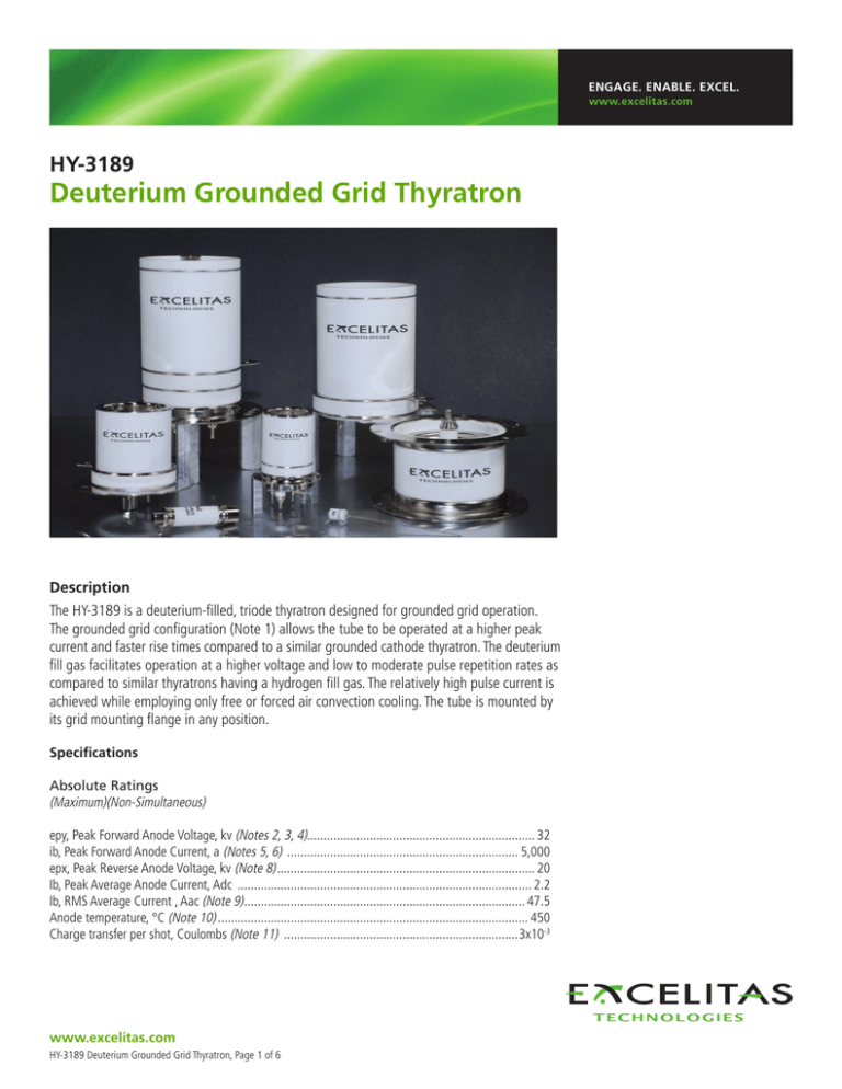
The HY-3189 is a deuterium-filled, triode thyratron designed for grounded grid operation.
The grounded grid configuration (Note 1) allows the tube to be operated at a higher peak
current and faster rise times compared to a similar grounded cathode thyratron. The deuterium
fill gas facilitates operation at a higher voltage and low to moderate pulse repetition rates as
compared to similar thyratrons having a hydrogen fill gas. The relatively high pulse current is
achieved while employing only free or forced air convection cooling. The tube is mounted by
its grid mounting flange in any position.
Specifications
Absolute Ratings
(Maximum)(Non-Simultaneous)
epy, Peak Forward Anode Voltage, kv (Notes 2, 3, 4)...................................................................... 32
ib, Peak Forward Anode Current, a (Notes 5, 6) ....................................................................... 5,000
epx, Peak Reverse Anode Voltage, kv (Note 8)............................................................................... 20
Ib, Peak Average Anode Current, Adc .......................................................................................... 2.2
Ib, RMS Average Current , Aac (Note 9)...................................................................................... 47.5
Anode temperature, °C (Note 10)............................................................................................... 450
Charge transfer per shot, Coulombs (Note 11) ........................................................................3x10-3
www.excelitas.com
HY-3189 Deuterium Grounded Grid Thyratron, Page 1 of 6
HY-3189
Deuterium Grounded Grid Thyratron
General Electrical Data
Ef, Cathode Heater Voltage, Vac .....................................................................................6.3±8%
If, Cathode Heater Current @ Ef=6.3 Vac, Aac ....................................................................12-18
Er, Reservoir Heater Voltage, Vac (Note 12)......................................................................6.3±8%
Ir, Reservoir Heater Current @ Er=6.3 Vac, Aac ............................................................. 3.0 nom.
Tk, Minimum Tube Warm-up Time, Minutes .............................................................................10
Trigger Driver Requirements
MIN TYP MAX.
Egy, Peak Open Circuit Driver Voltage, Negative Going
Applied to The Cathode, v.................................................. -450 ...............750 ............. -2500
Zg, Driver Circuit Output Impedance, Ohms .............................. --- .................100 ............... 250
Driver Pulse Rise Time, ns ......................................................... --- .................100 ............... 150
Driver Pulse Width, μs ............................................................... 1 ....................2 .................. --Peak Reverse Driver Voltage, v ................................................. --- ..................--- .................. --Bias Voltage, Positive, V ........................................................... --- ..................--- ................. 300
Triggering Characteristics
MIN TYP MAX.
Anode Delay Time, ns (Notes 13, 14)......................................... --- ..................--- ................. 500
Anode Delay Time Drift, ns (Note 14)........................................ --- ..................--- ................. 150
Time jitter, ns (Note 14)............................................................ --- ..................--- ................... 5
Current Rise Time, ns (Note 15)................................................. --- ...................7 .................. --Notes
1. This thyratron is designed to operate with the grid at chassis ground potential. The tube is driven into conduction by applying the triggering
pulse to the cathode lead. Therefore, the limits shown for egy are negative while the bias voltage is positive (i.e., the opposite polarity of what
would be the case for triggering a standard grounded cathode thyratron.
2. The dwell time at the peak anode voltage should be minimized in order to minimize prefiring. For operation at or above 30 kV, the dwell time
must not exceed 1 millisecond.
3. After thyratron anode current stops flowing and before voltage is reapplied to the anode, the anode voltage must stay between 0 and –500
volts for at least 100 μs to allow the gas to deionize.
4. This tube may be operated in air at up to 35 kv. Some of the more important derating factors that determine the safe operating voltage in air
are the cleanliness of the tube’s ceramic insulators, the rate of rise of anode voltage, the dwell time at the operating peak anode voltage, the
pulse repetition rate, and ambient pressure, temperature, humidity and contaminant level. This tube may also be operated while immersed in an
insulating gas or liquid.
5. The peak current capability of 20,000 amperes applies to low duty, short discharge duration (shorter than 150 nanoseconds) applications
without significant reverse current.
6. For anode current discharges longer than 150 nanoseconds or for discharge waveforms which exhibit significant current reversals use the
charge transfer per shot limitation for determination of the allowable peak current capability.
7. This tube is recommended for applications where the discharge current waveform has reversals. Each time the current reverses, the magnitude
of the current on that reversal must not exceed 60% of the magnitude of the current on the half cycle immediately preceding it.
8. The reverse anode voltage shown applies for a previously non-conducting tube. Exclusive only of a spike not longer than 25 nanoseconds, the
peak reverse anode voltage must not exceed 5kv during the first 50 microseconds after conduction.
www.excelitas.com
HY-3189 Deuterium Grounded Grid Thyratron, Page 2 of 6
HY-3189
Deuterium Grounded Grid Thyratron
Notes (cont.)
9. The root mean square anode current shall be computed as the square root of the product of the peak current and the absolute average current
when the reverse current is negligible. For cases where the reverse current is significant (i.e., where it exceeds 10% of forward current), this
simple relationship for calculation of the RMS current does not apply.
10. Forced air liquid immersion cooling should always be used in any situation where cooling by natural convection is insufficient to keep the
temperature of the tube’s envelope below 200°C. The anode temperature, measured on the external anode surface, should not be allowed to
exceed the value shown.
11. The charge transfer per shot includes the total charge conducted through the thyratron on that shot regardless of the direction of the flow of
the charge. In other words it is the time integral of the magnitude of the current over the duration of the discharge.
12. The optimum reservoir heater voltage is that which provides the best overall compromise among anode heating, anode voltage holdoff and
holdoff recovery, anode current rise rate, and the tube’s overall triggering characteristics. For the most applications, the optimum reservoir
heater voltage lies between 90% and 110% of the nominal value. Operation at voltages below 90% of nominal can result in permanent
damage from anode overheating; operation at high reservoir heater voltages degrades anode holdoff and holdoff recovery, and can
permanently damage the reservoir itself.
13. The anode delay time is measured from the 25% point on the rise of the unloaded grid voltage pulse to the 10% point on the rise of the anode
current pulse.
14. Delay time, delay time drift and time jitter may be simultaneously minimized by applying the maximum driver voltage (egy) from a source of low
impedance (Zg).
15. The current rise time is a function of the discharge circuit impedance. If care is exercised to reduce the inductance in the circuit, a typical rise
time on the order of that shown may be expected when using this thyratron.
16. All data and specifications are subject to change without notice.
www.excelitas.com
HY-3189 Deuterium Grounded Grid Thyratron, Page 3 of 6
HY-3189
Deuterium Grounded Grid Thyratron
FIGURE 1 Schematic
www.excelitas.com
HY-3189 Deuterium Grounded Grid Thyratron, Page 4 of 6
HY-3189
Deuterium Grounded Grid Thyratron
FIGURE 2 Schematic
www.excelitas.com
HY-3189 Deuterium Grounded Grid Thyratron, Page 5 of 6
HY-3189
Deuterium Grounded Grid Thyratron
About Excelitas Technologies
Excelitas Technologies is a global technology leader focused on
delivering innovative, customized solutions to meet the lighting,
detection, energetic, frequency standards and high-reliability power
needs of OEM customers.
From aerospace and defense applications to industrial, safety and
security, medical lighting, analytical instrumentation, and clinical
diagnostics, Excelitas Technologies is committed to enabling our
customers’ success in their specialty end-markets. Excelitas Technologies
has approximately 3,000 employees in North America, Europe and Asia,
serving customers across the world.
AES@excelitas.com
www.excelitas.com
Excelitas Technologies
Energetic Systems
1100 Vanguard Blvd.
Miamisburg, Ohio 45432
USA
Telephone: (+1) 937.865.3800
Toll Free: (+1) 866.539.5916
Fax: (+1) 937.865.5170
Excelitas Technologies
Power Supplies
1330 East Cypress Street
Covina, California 91724 USA
Telephone: (+1) 626.967.6021
Toll Free: (+1) 800.363.2095
Fax: (+1) 626.967.3151
Excelitas Technologies
Frequency Standards
& Switching
35 Congress Street
Salem Massachusetts 01970
USA
Telephone: (+1) 978.745.3200
Toll Free: (+1) 800.950.3441
Fax: (+1) 978.745.0894
Excelitas Technologies
Lighting & Radiant Sources
44370 Christy Street
Fremont, California 94538-3180
USA
Telephone: (+1) 510.979.6500
Toll Free: (+1) 800.775.6786
Fax: (+1) 510.687.1140
Excelitas Technologies
Sensors
22001 Dumberry Road
Vaudreuil-Dorion, Quebec
Canada J7V 8P7
Telephone: (+1) 450.424.3300
Toll Free: (+1) 800.775.6786
Fax: (+1) 450.424.3345
Excelitas Technologies
International Sales Office
Bat HTDS BP 246, 91882
Massy Cedes, France
Telephone: +33 (1) 6486 2824
For a complete listing of our global offices, visit www.excelitas.com/Locations
©2011, Excelitas Technologies Corp. All rights reserved. The Excelitas logo and design are registered trademarks of Excelitas Technologies Corp. All other trademarks
not owned by Excelitas Technologies or its subsidiaries that are depicted herein are the property of their respecitve owners. Excelitas reserves the right to change this
document at any time without notice and disclaims liabilitiy for editorial, pictorial or typographical errors.
HY-3189 Deuterium Grounded Grid Thyratron, Page 6 of 6


