Models SRG-A, SRG-LA, SRG-C and SRG-LC
advertisement
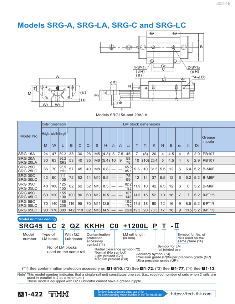
502-4E Models SRG-A, SRG-LA, SRG-C and SRG-LC B C2 C 4-S×ℓ1 ( φ H) (E) W L L1 φ d2 e0 2-S×ℓ2 ( φ H) ** 4- φ D0 f0 N T (K) M M1 h H3 W2 φ d1 W1 F Models SRG15A and 20A/LA Outer dimensions Model No. LM block dimensions Height Width Length M SRG 15A SRG 20A SRG 20LA SRG 25C SRG 25LC SRG 30C SRG 30LC SRG 35C SRG 35LC SRG 45C SRG 45LC SRG 55C SRG 55LC SRG 65LC 24 30 36 42 48 60 70 90 W L 47 69.2 86.2 106.2 95.5 70 115.1 111 90 135 125 100 155 155 120 190 185 140 235 170 303 63 B C 38 53 57 72 82 100 116 142 C2 S H ℓ1 ℓ2 Grease nipple L1 T T1 K N E e0 f0 D0 30 7 (8) 20 4 4.5 4 6 2.9 PB107 40 10 (10) 25.4 5 4.5 4 6 2.9 PB107 9.5 10 31.5 5.5 12 6 6.4 5.2 B-M6F 12 6.2 5.2 B-M6F 26 M5 (4.3) 8 7.5 45 58 35 M6 (5.4) 10 9 78 65.5 45 40 M8 6.8 — — 85.1 75 52 44 M10 8.5 — — 99 82.2 62 52 M10 8.5 — — 112.2 107 80 60 M12 10.5 — — 142 129.2 95 70 M14 12.5 — — 179.2 110 82 M16 14.5 — — 229.8 14 37 6.5 12 6 11.5 10 42 6.5 12 6 6 5.2 B-M6F 14.5 15 52 10 16 7 7 5.2 B-PT1/8 17.5 18 60 12 16 9 8.5 5.2 B-PT1/8 19.5 20 78.5 17 16 9 13.5 5.2 B-PT1/8 Model number coding SRG45 LC 2 QZ KKHH C0 +1200L P T -Ⅱ Model number Type of LM block With QZ Lubricator Symbol for No. of LM rail length Contamination rails used on the (in mm) protection same plane (*4) accessory symbol (*1) Symbol for LM No. of LM blocks Radial clearance symbol (*2) rail jointed use used on the same rail Normal (No symbol) Accuracy symbol (*3) Light preload (C1) Precision grade (P)/Super precision grade (SP) Medium preload (C0) Ultra precision grade (UP) (*1) See contamination protection accessory on A1-510. (*2) See A1-72. (*3) See A1-77. (*4) See A1-13. Note) This model number indicates that a single-rail unit constitutes one set. (i.e., required number of sets when 2 rails are used in parallel is 2 at a minimum.) Those models equipped with QZ Lubricator cannot have a grease nipple. A1-422 To download a desired data, search for the corresponding model number in the Technical site. https://tech.thk.com 502-4E SRG B (E) W φ d2 T T1 (K) M M1 L L1 4- φ D0 ** e0 f0 N h H3 W2 C2 C φ d1 W1 F Models SRG25 to 65C/LC Unit: mm LM rail dimensions Width Height Pitch Basic load rating Static permissible moment kN-m* MA MB MC Length* C C0 4 W1 0 -0.05 15 16 15.5 30 4.5×7.5×5.3 2500 4.6 20 21.5 20 30 6×9.5×8.5 3000 4.5 23 23.5 23 30 7×11×9 3000 5 28 31 26 40 9×14×12 3000 6 34 33 30 40 9×14×12 3000 8 45 37.5 37 52.5 14×20×17 3090 10 53 43.5 43 60 16×23×20 3060 11.5 63 53.5 54 75 18×26×22 3000 H3 W2 M1 F d1×d2×h Max kN kN 11.3 21 26.7 27.9 34.2 39.3 48.3 59.1 76 91.9 115 131 167 278 25.8 46.9 63.8 57.5 75 82.5 108 119 165 192 256 266 366 599 1 Double 1 Double 1 block blocks block blocks block 0.21 0.48 0.88 0.641 1.07 1.02 1.76 1.66 3.13 3.49 6.13 5.82 10.8 22.7 Mass LM block LM rail kg kg/m 1.24 0.21 1.24 0.24 0.20 2.74 0.48 2.74 0.58 0.42 4.49 0.88 4.49 0.79 0.57 3.7 0.641 3.7 0.795 0.7 5.74 1.07 5.74 1.03 0.9 6.21 1.02 6.21 1.47 1.2 9.73 1.76 9.73 1.92 1.6 10.1 1.66 10.1 2.39 1.9 17 3.13 17 3.31 2.4 20 3.49 20 4.98 3.7 32.2 6.13 32.2 6.64 4.5 33 5.82 33 8.19 5.9 57 10.8 57 11.2 7.8 120 22.7 120 22.1 16.4 1.58 2.58 3.6 4.4 6.9 11.6 15.8 23.7 Note1) The greasing hole on the top face and the pilot hole of the side nipple* are not drilled through in order to prevent foreign material from entering the block. THK will mount a grease nipple per your request. Therefore, do not use the greasing hole of the top face and the side nipple pilot hole* for purposes other than mounting a grease nipple. In case of oil lubrication, be sure to let THK know the mounting orientation and the exact position in each LM block where the piping joint should be attached. For the mounting orientation and the lubrication, see A1-12 and A24-2, respectively. The maximum length under “Length*” indicates the standard maximum length of an LM rail. (See A1-428.) Static permissible moment*: 1 block: static permissible moment value with 1 LM block Double blocks: static permissible moment value with 2 blocks closely contacting with each other Note2) If the mounting holes (4 holes) of the LM block are back spot-faced, these models can be mounted on the table from the top and the bottom as with model SRG-C. The value in the parentheses represents a dimension if the mounting hole is back spot-faced. Contact THK for details. Options⇒A1-473 A1-423 LM Guide 6-S ( φ H through)

