Standard Device - Electrical and Computer Engineering at Carnegie
advertisement
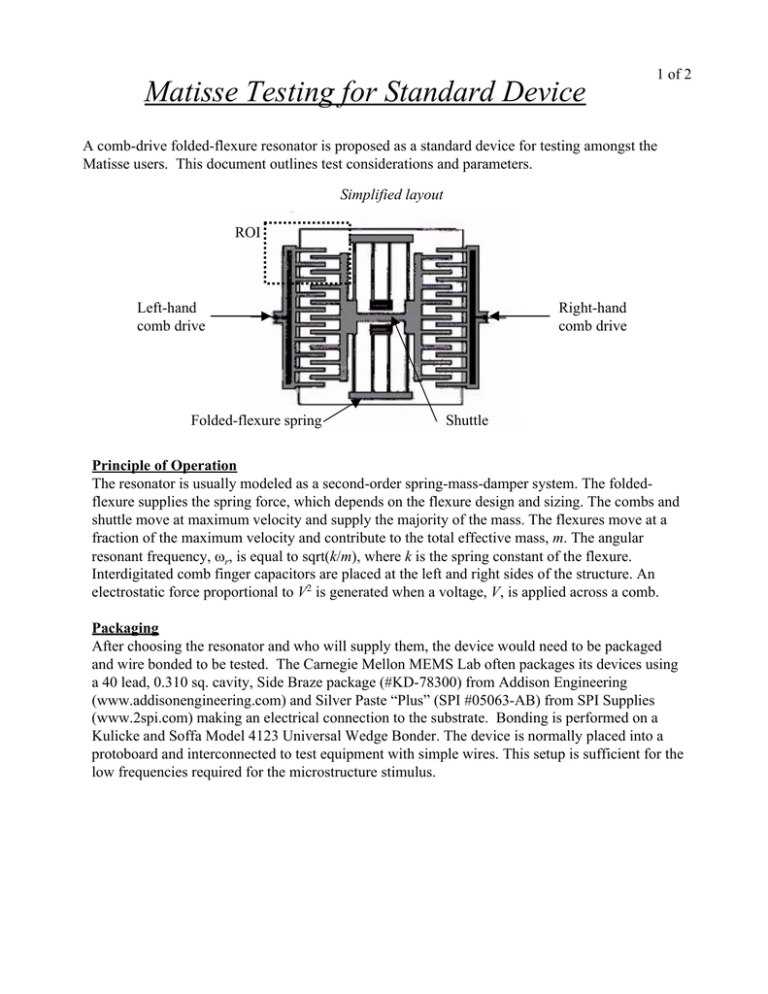
Matisse Testing for Standard Device 1 of 2 A comb-drive folded-flexure resonator is proposed as a standard device for testing amongst the Matisse users. This document outlines test considerations and parameters. Simplified layout ROI Left-hand comb drive Folded-flexure spring Right-hand comb drive Shuttle Principle of Operation The resonator is usually modeled as a second-order spring-mass-damper system. The foldedflexure supplies the spring force, which depends on the flexure design and sizing. The combs and shuttle move at maximum velocity and supply the majority of the mass. The flexures move at a fraction of the maximum velocity and contribute to the total effective mass, m. The angular resonant frequency, ωr, is equal to sqrt(k/m), where k is the spring constant of the flexure. Interdigitated comb finger capacitors are placed at the left and right sides of the structure. An electrostatic force proportional to V2 is generated when a voltage, V, is applied across a comb. Packaging After choosing the resonator and who will supply them, the device would need to be packaged and wire bonded to be tested. The Carnegie Mellon MEMS Lab often packages its devices using a 40 lead, 0.310 sq. cavity, Side Braze package (#KD-78300) from Addison Engineering (www.addisonengineering.com) and Silver Paste “Plus” (SPI #05063-AB) from SPI Supplies (www.2spi.com) making an electrical connection to the substrate. Bonding is performed on a Kulicke and Soffa Model 4123 Universal Wedge Bonder. The device is normally placed into a protoboard and interconnected to test equipment with simple wires. This setup is sufficient for the low frequencies required for the microstructure stimulus. Matisse Testing for Standard Device 2 of 2 Symbolic schematic Vac = Vamp cos(ω t) Vdc Stimulus The schematic above shows the three electrical connections for a symmetric two-port resonator. Vdc is a dc bias voltage applied to the central moving shuttle using a dc power supply. Vac is a sinusoidal input voltage applied to the left stator comb drive while the other stator comb drive is held at ground. The sinusoidal voltage is normally controlled by the Microvision system with an amplitude Vamp and angular frequency ω. Vamp is kept at least 5X smaller than Vdc so the dc force acting on the shuttle is small, while the ac force is primarily contributed by the VdcVamp cos(ω t) term. A smaller V2amp cos(2ω t) term is also present and will create detectable motion. Testing Testing the device involves sweeping the frequency from fstart to fstop either linearly or logarithmically by a defined number of steps (e.g., 20). This frequency range is selected to include the resonant frequency fr. The number of phases (e.g., 8) and number of focal planes (e.g., 4) are defined to maintain consistency between tests. Increasing these parameters will improve the accuracy of the tests but increase the required time. The step size for the focal planes (e.g., 0.5µm) will be dependent on the number of focal planes used and the expected range of motion for the resonator. A microscope objective power for the test is specified (e.g., 20X). The region of interest (ROI) will be the upper left hand corner of the resonator to include the top left rotor and stator fingers. Data Analysis A differential measurement (dots) is used for analysis of the data to generate bode plots for x, y and z motion. These bode plots identify the resonant frequencies. Within the ROI, the edge of the top left rotor finger may be defined as one point for analysis. The other point may be the edge of the stator anchor opposite that rotor finger. Data Comparison Testing multiple chips of this standard device on the same instrument will establish a lower error boundary for comparison with testing on different instruments. Results from different instruments are expected to verify the accuracy and repeatability of the experimental methodology.
