SAW BASED TRANSMITTER DESIGN NOTES
advertisement
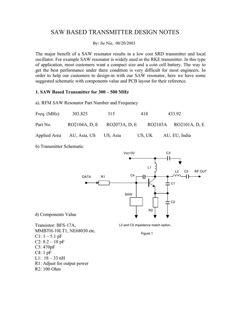
SAW BASED TRANSMITTER DESIGN NOTES By: Jie Nie, 08/20/2003 The major benefit of a SAW resonator results in a low cost SRD transmitter and local oscillator. For example SAW resonator is widely used in the RKE transmitter. In this type of application, most customers want a compact size and a coin cell battery. The way to get the best performance under there condition is very difficult for most engineers. In order to help our customers to design-in with our SAW resonator, here we have some suggested schematic with components value and PCB layout for their reference. 1. SAW Based Transmitter for 300 – 500 MHz a). RFM SAW Resonator Part Number and Frequency Freq. (MHz) Part No. Applied Area 303.825 315 RO2104A, D, E AU, Asia, US 418 RO2073A, D, E US, Asia 433.92 RO2103A US, UK RO2101A, D, E AU, EU, India b) Transmitter Schematic Vcc=3V C3 L1 L2 DATA R1 C4 C1 SAW C2 R2 d) Components Value Transistor: BFS-17A, MMBTH-10LT1, NE68030 etc. C1: 1 – 5.1 pF C2: 8.2 – 18 pF C3: 470pF C4: 1 pF L1: 18 – 33 nH R1: Adjust for output power R2: 100 Ohm L2 and C5 impedance match option.. Figure 1 C5 RF OUT 2. SAW Based Transmitter for 800 – 1000 MH a). RFM SAW Resonator Part Number and Frequency Freq. (MHz) Part No. Applied Area 868.35 916.5 RO2164A, D, E AU, EU RO2144A, D, E US, b) Transmitter Schematic Vcc=3V C3 L1 L2 DATA R1 C1 SAW C2 R2 L2 and C5 impedance match option.. Figure 2 d) Components Value Transistor: MMBR-901, NE68030 etc. C1: 1 – 2.2 pF C2: 5.1 – 8.2 pF C3: 220pF L1: 3.9 – 6.8 nH R1: Adjust for output power R2: 100 Ohm C5 RF OUT 3. PCB Layout Dimensions: 0.5" x 0.6" SAW Based Transmitter Design Notes Rev.012406
