Taming slug flow in pipelines
advertisement
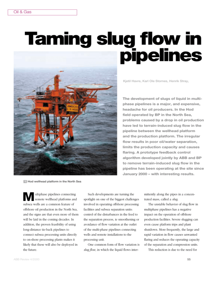
Oil & Gas Taming slug flow in pipelines Kjetil Havre, Karl Ole Stornes, Henrik Stray, The development of slugs of liquid in multiphase pipelines is a major, and expensive, headache for oil producers. In the Hod field operated by BP in the North Sea, problems caused by a drop in oil production have led to terrain-induced slug flow in the pipeline between the wellhead platform and the production platform. The irregular flow results in poor oil/water separation, limits the production capacity and causes flaring. A prototype feedback control algorithm developed jointly by ABB and BP to remove terrain-induced slug flow in the pipeline has been operating at the site since January 2000 – with interesting results. 1 Hod wellhead platform in the North Sea M ultiphase pipelines connecting remote wellhead platforms and subsea wells are a common feature of offshore oil production in the North Sea, and the signs are that even more of them will be laid in the coming decades. In addition, the proven feasibility of using long-distance tie-back pipelines to connect subsea processing units directly to on-shore processing plants makes it likely that these will also be deployed in the future. ABB Review 4/2000 Such developments are turning the spotlight on one of the biggest challenges involved in operating offshore processing facilities and subsea separation units: control of the disturbances in the feed to the separation process, ie smoothening or avoidance of flow variation at the outlet of the multi-phase pipelines connecting wells and remote installations to the processing unit. One common form of flow variation is slug flow, in which the liquid flows inter- mittently along the pipes in a concentrated mass, called a slug. The unstable behavior of slug flow in multiphase pipelines has a negative impact on the operation of offshore production facilities. Severe slugging can even cause platform trips and plant shutdown. More frequently, the large and rapid variation in flow causes unwanted flaring and reduces the operating capacity of the separation and compression units. This reduction is due to the need for 55 Oil & Gas larger operating margins for both separation (to meet the product specifications) and compression (to ensure safe operation with minimum flaring). Backing off from the plant’s optimal operating point in this way reduces its throughput. A lot of money and effort has therefore been spent trying to avoid the problem associated with slug flow, for example by installing slug catchers on-shore or What are slugs? increasing the size of the first-stage separators to provide the necessary buffer capacity. However, design changes of this kind are inappropriate for installations already experiencing slug flow problems and for compact separation units [1]. An alternative to process design changes is to reduce the effect of the slug by feed-forward control. The idea here is to detect the build-up of slugs and to Oil produced offshore is Slug transported through pipelines as a complex Gas pocket Gas pocket Film prepare the separators to receive them, eg via feed-forward control to the separator level and pressure control loops. A drawback of this approach, however, is that the volume of the separator unit is used as a buffer instead of for actual separation. Besides, feed-forward control is not very robust due to model uncertainty [2]. A third approach involves detecting the build-up of slugs and then using the Where does slug theory stand today? Slug flow research has been going on for many mixture of oil, gas water and years, and various sand. One common flow regime is known as slug flow, approximate methods have been developed for in which the liquid flows intermittently along the pipes in calculating slug hydrodynamics. In the past, these have a concentrated mass, called a slug. relied on correlation with experimental data, but more Understanding slug flow is made difficult by its transient recently modeling has been used to simulate the flow nature and the multi-dimensional fluid dynamic process that behavior sufficiently accurately to calculate pressure drops characterizes it. Because slug flow is highly complex and and other flow parameters with relative confidence. unstable, it is difficult to predict the pressure drop, heat and These models, however, consider steady slug flow, mass transfer. In addition, the flow nature will vary depending in which the slug moves with constant velocity, so that the on whether the pipeline is horizontal, vertical or inclined! characteristic slug intermittency and irregularity are less well described. Why are slugs a problem? Current research tends to target measurement and The arrival of a slug at production or processing modeling of the development of liquid slug length equipment is unwelcome to say the least. Severe slugging distribution along the pipe as well as the dependence of can even cause platforms to automatically shut down. various pipeline and flow parameters on the flow velocities. Slug flow starts with an accumulation of oil and water in Knowledge of the time-averaged flow values may be low-lying parts of the pipeline. Gas collects downstream of inadequate due to an absence of information about the this growing slug, causing an increase in pressure. When longitudinal distribution, which is often essential. Slug the pressure reaches a certain level, the slug begins to catchers, for example, which should eliminate slugs, are move towards the pipeline outlet, followed by the gas. This designed on the basis of the maximum slug length and not process then repeats itself. the average. 56 ABB Review 4/2000 2 Valhall production platform. Due to a drop in oil production, slugs of liquid develop in the pipeline between the Hod and Valhall platforms, resulting in poor water/oil separation and causing flaring. unstable multiphase fluid flow regimes are key to the feasibility of compact separation units for both topside and subsea use. The Hod-Valhall site ABB Review 4/2000 of the method are foreseen for remove riser-induced slug flow and combinations of hydrodynamic induced slug flow and terrain-induced slug flow (the latter occurs frequently in pipelines connecting wells to the production facility). In fact, overcoming the problem of slug flow and creating control solutions that prevent 3 Schematic of the Hod-Valhall offshore site. The pipeline instrumentation includes flow transmitters (FT), pressure transmitters (PT) and temperature transmitters (TT). To flare Valhall wells Hod platform Hod wells pipeline choke to reduce their effect on the separator unit [3]. The main problem with this approach is that if the algorithm causes the choke to close too much, the slug returns to the bottom of the pipe and an even larger slug is formed. In the case of the Hod-Valhall site in the North Sea, none of these approaches offered the hoped-for results. Design changes on the Valhall platform were not a realistic option, feed-forward slug control was found to be not robust enough, and choking in the presence of slugs did not work in the Hod-Valhall pipeline. A fourth approach was therefore devised. Its underlying idea is to remove the slug flow regime by applying active feedback control, and thereby prevent the slug from entering the production process at the Valhall platform. ABB has a considerable interest in the results of the Hod-Valhall pipeline project and in applying them to other types of slug phenomena. For instance, variations The Hod-Valhall site consists of an unmanned, remote-controlled wellhead platform, Hod 1 , a 13-km-long multiphase pipeline, and the main production platform, Valhall 2 . The gas, oil and water produced at Hod are transported through the pipeline to the Valhall platform, where it is merged with the oil produced by the Valhall wells 3 . The combined stream then enters the separation unit, which consists of two first-stage and two second-stage separators in parallel. At the Hod and Valhall platforms the water depth is approximately 70 meters. The profile of the pipeline, which has a diameter of 12 inches, is shown in 4 . Included in the pipeline Separator FT 1st stage separator PT FT TT PT 70 m 2nd stage separator TT Valhall platform 12-inch pipeline, 13 km long 57 Oil & Gas 4 Hod-Valhall pipeline profile 5 Results of open-loop simulation of the Hod Valhall pipeline (two slug cycles) H Height/depth a Pressure (p) at pipeline inlet (Hod, blue) and outlet (Valhall, green) D Distance b Gas (G, brown) and liquid (L, orange) flow rates at pipeline outlet t Time 30 Simulations performed with the dynamic multiphase simulator OLGA, using the S e a le v e l OLGA/MATLAB link developed by ABB -10 -30 -50 130 -70 4 6 8 D [km] 10 12 instrumentation are pressure and temperature transmitters at Hod and a pressure transmitter upstream of the pipeline choke at Valhall. The gas and liquid flows from the Hod wells are measured separately at the outlet of a test separator before the streams enter the pipeline to Valhall. Despite the fact that the wells at the Hod platform produce less than 5% of the total produced by the wells at the Valhall platform, the slugs are large and intense enough to cause considerable operational problems. These problems include: Large disturbances in the separator train, causing: – Poor separation (water carry-over to the export pipeline due to rapidly varying separator feed rates. – Varying water quality at the separator water outlets, leading to major problems in the downstream water treatment system and possible violation of environmental restrictions. ■ Large and rapidly varying compressor loads, causing: – Inefficient compressor operation. – Limited compression capacity due to a larger margin being needed to handle gas hold-up behind the liquid. ■ 58 110 100 90 a 2.0 20 1.5 15 1.0 10 0.5 5 0 L [kg/s] 2 p [p s i] 120 0 G [kg/s] H [m ] 10 0 20 21 22 b – Spurious flaring (a result of the limited compression capacity. Large pressure variations at the Hod end of the pipeline, which are also visible in the Hod wells. Wells with a reduced lifting capacity produce less. ■ Terrain-induced slug flow cycle Terrain-induced slug flow – the cause of the problems at the Hod-Valhall site – develops in five stages: Liquid build-up: Terrain-induced slug flow is initiated by a period during which liquid, oil and water accumulate in the lower parts of the pipeline or at the bottom of the riser. Pressure build-up: After a certain time, the liquid will block the passage of the gas. Some of the gas will bubble through the liquid plug, but most of 23 24 25 26 t [h] it accumulates upstream, causing an increase in pressure. Mass acceleration: At a certain pressure, the liquid plug starts moving due to forces acting on it. Mass transportation: Depending on the pipeline geometry downstream, the liquid plug and the operating conditions, the plug may either die out or be transported to the outlet of the pipeline/riser. Pressure reduction: As the gas and liquid are transported out of the pipeline, the upstream pressure decreases and the liquid flow from the pipeline ceases. The process then starts over again, resulting in an unstable multiphase flow pattern in which the liquid flow rate varies from zero to a significant value in one cycle, called the terrain-induced slug flow cycle. ABB Review 4/2000 6 Profile of the liquid volume fraction (LVF) through a slug in the Hod-Valhall pipeline. Each line represents the liquid volume fraction pipeline profile at a certain time (sample interval 60 s, time scope 22 h to 24 h). D Distance the cycle. Positions where the difference between the maximum and the minimum liquid volume fractions are large have the potential to initiate terrain-induced slug flow. 0.7 0.6 The slug controller The intuitive approach to the problem of slug flow is to detect the slug and try to limit its size in order to restrict the effect it has on the separator train and compressors at the production facility. With its new slug controller, SlugConTM, ABB has taken yet another approach in the sense that it stabilizes the flow and thereby avoids slug formation. The slug controller software has the following functionality: 0.5 LV F [–] 0.4 0.3 0.2 0.1 0 0 2 4 6 D [km] Multiphase fluid flow simulation The Hod-Valhall pipeline was simulated using the multiphase fluid flow simulator OLGA. Application-specific data entered in the simulator included: ■ Fluid characterization of the Hod oil ■ Pipeline profile, diameters and material ■ Data for the pipeline choke and its position The model that was used is capable of simulating terrain-induced slug flow with approximately the same dynamics as those experienced by the pipeline. It should be said that some discrepancies were observed between the real pipeline data and the simulations of pressure at the inlet of the pipeline (Hod). Also, no effort was made to tune the multiphase model to the real pipeline. ABB Review 4/2000 8 10 12 Slug control: – Dynamic feedback control: to ensure stable operation of the pipeline. The pipeline simulations shown in 5 – Slug choking: to limit the effect the slug were performed with a constant feed rate has on the separation and compression of 3 kg/s at the inlet, without control. It is units. seen that the liquid flow rate at the pipeline – Feed-forward control: to adjust the output is zero for a period of about 2 hours. nominal operating point and parameters During this time the pressure upstream of in the dynamic feedback controller. the liquid plug builds up. When it exceeds ■ Slug signature: for detecting slugs and the hydrostatic pressure of the liquid monitoring the performance of the column in the riser, the liquid accelerates dynamic feedback controller. and the pressure rises at the pipe outlet. ■ Interface to separator train control: The liquid is transported to the outlet of – Separator feed-forward control the pipe and the pressure decreases as the – Override slug control (in case of a fault gas and liquid escapes through the pipeline. or error in the separator train) The process then repeats itself. ■ Operator interface: 6 shows the pipeline profile plot of – Starting and stopping the controller the liquid volume fraction, sampled each – Starting/stopping logging minute during one slug cycle. It is not – Monitoring the performance of the what happens at different times which is feedback controller important here, but what happens at – Trends and graphs different positions in the pipeline during – Access to controller parameters ■ 59 Oil & Gas 60 7 Slug controller feedback structure for flow stabilization For explanation of symbols, see Fig. 3. Feed-forward FT FT Hod Valhall Dynamic feedback controller PT 1 PT 2 PT 3 Slug signature Hod-Valhall pipeline 8 Active control of terrain-induced slug flow. The controller starts up at t = 28 h and runs until t = 45 h, after which the valve position is kept constant and slug flow slowly builds up. Pressure at pipeline inlet (Hod, blue) and outlet (Valhall, green) G Gas flow rate (brown) L Liquid flow rate (orange) V Valve opening t Time b 130 120 110 100 30 20 10 0 Controller in manual mode Controller starts 15 10 5 0 1.5 1.0 0.5 0 20 25 Slug flow 30 35 t [h] 40 Stabilizing control 45 50 L [k g/ s ] V [ %] p [ps i] p G [k g/ s ] The slug controller configuration in 7 shows how pressure measurements at the inlet and outlet of the pipeline are used to adjust the pipeline choke valve. If flow measurements are available, they are also used for feed-forward control of the nominal operating point and tuning parameters of the controller. The simulated performance of the slug controller is shown in 8 . During the first eight hours the controller is in manual mode, as indicated by the characteristic pressure swings in the pipeline inlet and outlet pressure. The controller starts at t=28h and spends the next 5 to 7 hours stabilizing the pipeline. The controller seems to have settled at a constant output value at t=38h. However, this is not true. If the control value were magnified, it would be seen that it moves constantly around its mean value. The controller is set to manual at t=45h, with its output equal to the mean value over the previous 3 hours. Afterwards, the slug flow builds up slowly. It appears to be unrealistic to try and prove global stability mathematically. Nevertheless, from 8 it seems reasonable to assume that the pipeline flow is stable at least at the input and at the output, since the pressures are stable. However, due to the length of the pipeline it could be claimed that internal instability might occur in it. 9 shows profile plots of the liquid volume fraction, sampled at 60-second intervals between t=41h and t=45h. 241 plots are therefore shown. They all lie on top of each other, implying that stability is achieved throughout the pipeline. Slug flow (build-up) ABB Review 4/2000 Control theory has this to say about stabilizing unstable systems In order to stabilize an unstable system, the control loop In unstable systems, sensitivity to disturbances and needs to have a certain minimum bandwidth (see [4], measurement noise can be quite high (see [5], section chapter 5, page 184). In practice, this means that the 4.5.2, page 78 and section 4.6, page 82). Because measurement has to take place, and the controller and of this, the input (pipeline choke) easily enters a state the actuator (pipeline choke) have to react, faster than the of saturation, with a resulting loss of stability. instability can develop. Otherwise, the control loop will not It is therefore important to minimize the amount of be able to counteract the instability. Thus, the control loop measurement noise. is not allowed to exhibit any unnecessary delays. The prototype of the slug controller was tested twice in 1999 and has been operating at the Hod-Valhall site since the end of January 2000. 10 to 13 show some of the slug controller test results: ■ 10 and 11 show controller start-up and operation with a low pipeline flow rate (two wells are started up). ■ 12 and 13 show controller operation for start-up of a major well and controller stop with a high pipeline flow rate. In order to understand the test results it is important to know that the wells at Hod are operated cyclically, as the well flow rate decreases over time. When production from a well has reached a lower limit, the well is put on hold. The operating time and the hold time differ from well to well; some of the wells only remain in operation for a couple of days before being put on hold. 10 and 11 show the slug controller in operation. During the first eight hours the choke (see 10 ) is opened manually to 20%. Under such conditions the terrain induced slug flow cycle can be seen well. ABB Review 4/2000 At 11:18 AM, the startup condition is fulfilled and the controller starts updating the choke. The choke is only allowed to be open in the range of 5% to 35%. The controller stabilizes the pipeline for the next 36 hours. From 10 it can be seen that the mean pipeline inlet pressure decreases considerably when no slug cycles appear. During the four days and 6 hours shown in the figures, two of the Hod wells that had been on hold were taken into operation, the first on October 4 (at 4 AM) and the second on October 5 (12 AM), as shown by the pressure spikes in the plots. A well start-up represents a large disturbance to the slug controller, and can introduce instability into the pipeline. As 10 shows, a terrain-induced slug flow cycle appears just after the first well start-up. 11 shows the pipeline input flow rate. During the first 19 hours the Hod wells bypassed the test separator (which is why the pipeline inlet flow rates during that time are missing). Although the changes in the pipeline input flow 9 Pipeline profile of the liquid volume fraction (LVF) with slug control (compare Fig. 6, without slug control). 241 profile plots are shown. Sampling interval 60 s. All lines lie on top of each other, implying that the whole pipeline is stable. 0.7 0.6 0.5 LV F [ -] Field tests S lug c ontro l 0.4 0.3 0.2 0.1 0 D Distance 0 2 4 6 D [km] 8 10 12 61 Oil & Gas 10 Slug controller in operation with a low pipeline flow rate and well start-ups. Pressure p at the pipeline inlet (Hod, blue) and outlet (Valhall, green), plus choke position C. Also shown is the 12-hour moving average of the pipeline pressures. 250 12h M A p [p s i] 200 150 100 40 C [ %] 30 20 10 0 00:00:00 2000-10-02 11 +12 +12 00:00:00 2000-10-03 00:00:00 2000-10-04 +12 00:00:00 2000-10-05 +12 00:00:00 2000-10-06 Slug controller in operation with a low pipeline flow rate and well start-ups. 30-minute and 8-hour moving average (MA) of the gas (G) and liquid (L) mean flow rates at the pipeline inlet (Hod). 2500 G [M SC FD] 2000 3 0m in M A 8h MA 1500 1000 500 0 4000 L [ bb l/ d] 3000 3 0m in M A 8h MA 1000 0 62 +12 00:00:00 2000-10-03 Smaller disturbances in the separator train, resulting in smoother operation: – Improved separation – Higher throughput ■ Smoother operation of the compressors: – More stable compressor operation and reduced flaring. Given the ‘stable’ inlet ■ 2000 00:00:00 2000-10-02 rates, plus the well start-up, constitute major disturbances, the slug controller copes quite well, proving that the chosen control scheme for the slug controller is robust under such conditions. 12 and 13 show the slug controller operating under a new set of conditions. When well H8 was taken into operation on May 1 at 10 AM, the controller was already in auto mode. The high pressure caused the controller to saturate at 35%; when the pressure drops the pipeline become stable. The controller was stopped at 8 PM on May 2, and terrain-induced slug flow with growing amplitude in the pressure swings is seen to form in the hours afterwards. It should also be noted how the pipeline inlet liquid flow rate drops when terrain-induced slug flow appears. The varying flow rates and the cyclic operation of the Hod platform wells make it very difficult to determine conclusively the extent to which the slug controller affects the Hod wells – ie, whether the wells produce less, more, or about the same as before the slug controller was installed. Recent experience indicates that the wells can be kept operating longer, which increases production. This is particularly true in the case of well H8. Additional benefits that the slug controller has brought to the Valhall platform include: +12 00:00:00 2000-10-04 +12 00:00:00 2000-10-05 +12 00:00:00 2000-10-06 ABB Review 4/2000 12 Effect of slug control with a high pipeline flow rate and well start-ups. Pressure p at the pipeline inlet (Hod, blue) and outlet (Valhall, green), plus choke position C. Also shown is the 12-hour moving average of the pipeline pressures. 250 1 2 h MA 200 p [p s i] and outlet pipeline pressure, and also the insights provided by the multiphase flow simulation, it is reasonable to state that the slug controller greatly improves the stability of multiphase flow in the pipeline. 150 100 0 The slug tamed 30 C [% ] Besides demonstrating how active feedback control can be used to avoid terrain-induced slug flow without reducing oil production, the tests with the prototype algorithm have served to underscore the huge potential that exists for applying active feedback control to multiphase fluid flow processes. 40 20 10 0 00:00:00 2000-05-01 +12 00:00:00 2000-05-02 +12 00:00:00 2000-05-03 +12 +12 00:00:00 2000-05-04 Authors 13 Kjetil Havre ABB Corporate Research AS Billingstad, Norway kjetil.havre@no.abb.com Telefax: +47 66 843541 Henrik Stray ABB Industri AS Oslo, Norway Telefax: +47 22 37 74 23 pipeline inlet (Hod). 12000 3 0 m i n MA 8 h MA 10000 8000 L [ b bl/ d] Karl Ole Stornes BP Stavanger, Norway Storneko@bp.com Telefax: +47 52 01 30 01 Effect of slug control with a high pipeline flow rate and well start-ups. 30-minute and 8-hour moving average (MA) of the liquid (L) mean flow rate at the 6000 4000 2000 0 00:00:00 2000-05-01 +12 00:00:00 2000-05-02 +12 00:00:00 2000-05-03 +12 00:00:00 2000-05-04 +12 References [1] G. Haandrikman, R. Seelen, R. Henkes, R. Vreenegoor: Slug control in flowline/riser systems. Proc 2nd Int Conf: Latest Advances in Offshore Processing, Nov 9–10 1999, Aberdeen, UK. [2] S. Skogestad, K. Havre: The use of RGA and condition number as robustness measures. Proc European Symposium on Computer-Aided Process Engineering (ESCAPE’96), Rhodes, Greece, May 1996. [3] Z.G. Xu, P. Gayton, A. Hall, J. Rambæk: Simulation study and field measurement for mitigation of slugging problems in the Hudson transportation lines. Proc Multiphase ’97, Cannes, France, June 1997. [4] S. Skogestad, I. Postlethwaite: Multivariable Feedback Control, Analysis and Design. John Wiley & Sons, Chichester, UK, 1996. [5] K. Havre: Studies on controllability analysis and control structure design. PhD thesis, Norwegian University of Science and Technology, Trondheim, 1998. ABB Review 4/2000 63
