Selection Table for SCCR Power Distribution Blocks and Power
advertisement
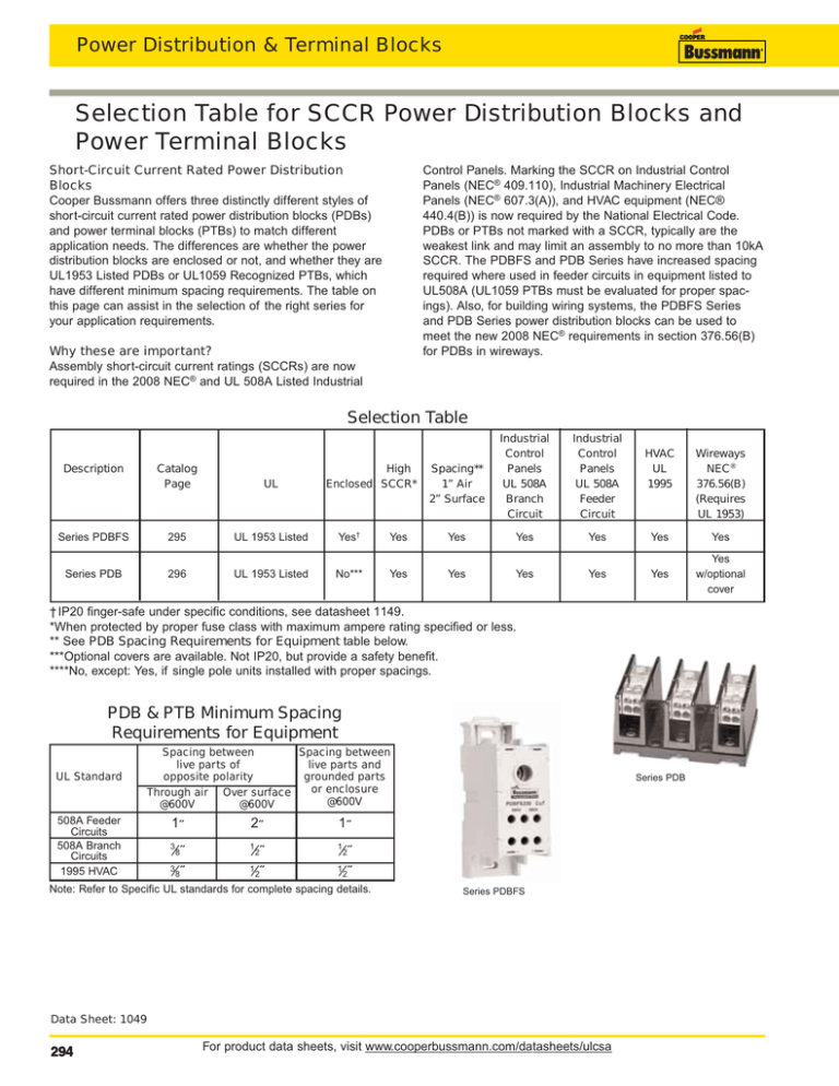
Power Distribution & Terminal Blocks Selection Table for SCCR Power Distribution Blocks and Power Terminal Blocks Short-Circuit Current Rated Power Distribution Blocks Cooper Bussmann offers three distinctly different styles of short-circuit current rated power distribution blocks (PDBs) and power terminal blocks (PTBs) to match different application needs. The differences are whether the power distribution blocks are enclosed or not, and whether they are UL1953 Listed PDBs or UL1059 Recognized PTBs, which have different minimum spacing requirements. The table on this page can assist in the selection of the right series for your application requirements. Control Panels. Marking the SCCR on Industrial Control Panels (NEC® 409.110), Industrial Machinery Electrical Panels (NEC® 607.3(A)), and HVAC equipment (NEC® 440.4(B)) is now required by the National Electrical Code. PDBs or PTBs not marked with a SCCR, typically are the weakest link and may limit an assembly to no more than 10kA SCCR. The PDBFS and PDB Series have increased spacing required where used in feeder circuits in equipment listed to UL508A (UL1059 PTBs must be evaluated for proper spacings). Also, for building wiring systems, the PDBFS Series and PDB Series power distribution blocks can be used to meet the new 2008 NEC® requirements in section 376.56(B) for PDBs in wireways. Why these are important? Assembly short-circuit current ratings (SCCRs) are now required in the 2008 NEC® and UL 508A Listed Industrial Selection Table Description High Enclosed SCCR* Spacing** 1” Air 2” Surface Industrial Control Panels UL 508A Branch Circuit Industrial Control Panels UL 508A Feeder Circuit Catalog Page UL Series PDBFS 295 UL 1953 Listed Yes† Yes Yes Yes Series PDB 296 UL 1953 Listed No*** Yes Yes Yes HVAC UL 1995 Wireways NEC® 376.56(B) (Requires UL 1953) Yes Yes Yes Yes Yes Yes w/optional cover † IP20 finger-safe under specific conditions, see datasheet 1149. *When protected by proper fuse class with maximum ampere rating specified or less. ** See PDB Spacing Requirements for Equipment table below. ***Optional covers are available. Not IP20, but provide a safety benefit. ****No, except: Yes, if single pole units installed with proper spacings. PDB & PTB Minimum Spacing Requirements for Equipment UL Standard Spacing between Spacing between live parts of live parts and opposite polarity grounded parts or enclosure Through air Over surface @600V @600V @600V 508A Feeder Circuits 508A Branch Circuits 1995 HVAC 1˝ 2˝ 1˝ 3 1 1 ⁄8˝ 3⁄ ˝ 8 ⁄2˝ 1⁄ ˝ 2 Series PDB ⁄2˝ ⁄2˝ 1 Note: Refer to Specific UL standards for complete spacing details. Series PDBFS Data Sheet: 1049 294 For product data sheets, visit www.cooperbussmann.com/datasheets/ulcsa Power Distribution & Terminal Blocks Series PDB of Power Distribution Blocks Electrical • 600Vac/dc (UL 1953) • Short-circuit current ratings up to 200kA, see table • Wire range 14 AWG to 350 kcmil Cu • Spacing between uninsulated opposite polarities or ground meets UL 1953 which requires at least 1” through air and 2” over surface • Ratings available with circuit breakers Feature/Benefits • High short-circuit current ratings up to 200kA. These PDBs do not have to be the weak link in achieving high SCCR for an industrial control panel • Listed to UL 1953 which has minimum spacing requirements at 600V of at least 1” through air and 2” over surface required for feeder in UL 508A Industrial Control Panels • For 2D CAD drawings visit www.cooperbussmann.com Agency/Standards • UL Listed 1953, Guide QPQS, File E256146 Mechanical • Panel mount • Flammability, UL 94V0 • Tin-plated Al connectors suitable for Cu conductors Optional covers Covers are ordered for each individual pole, i.e., three 1-pole covers for 3-pole block, see table A. Except PDB321 blocks have one cover for 1, 2 or 3 pole versions, see table B. Table A Table B Block Cover Block Cover PDB2XX-(pole): CPB162-1 PDB321-1 CPDB-1 PDB3XX-(pole): CPDB-1 PDB321-2 CPDB-2 PDB321-3 CPDB-3 Series PDB Terminal Copper Conductor Capability Line Load Configuration Catalog Number Openings per Pole Amps - Wire Range Wire Range Line Pole Load Short-Circuit Current Rating Data Conductors Max Fuse Class & Amp* Line Load J T RK1 RK5 AWG or kcmil AWG or kcmil LPJ JJS JJN LPS-RK LPN-RK FRS-R FRN-R 2/0 - 8 200 200 200 60 200kA 4 - 12 200 200 175† 175† 200† 200† 200† 100† 100† 60† 60† 60† 200kA 100kA 50kA 200 200 100 60 200kA 400 400† 14 175† 400 4-8 400† 10 - 12 175† 4-8 400 400† 10 - 14 175† 1/0 - 6 400† 400 8 - 12 175† 400 400† 175† 400 400† 175† 400 400† 175† 400 400† 200† 400† 100† 200† 400† 100† 200† 400† 100† 200† 400† 100† 100† 60† 100† 100† 60† 100† 100† 60† 100† 100† 200kA 100kA 100kA 200kA 100kA 100kA 200kA 100kA 100kA 200kA 100kA 175† 100† 60† 100kA PDB204-1 PDB204-3 175A 2/0 - 8 AWG 2/0 - 8 AWG 2/0 - 8 PDB220-1 PDB220-3 175A 2/0 - 8 AWG 4 - 14 AWG 2/0 - 8 PDB280-1 PDB280-3 175A 2/0 - 8 AWG 1/4-20 X 3/4 STUD 2/0 - 8 PDB321-1 PDB321-2 PDB321-3 175A PDB323-1 PDB323-3 2/0 - 8 AWG 4 - 14 AWG 2/0 - 8 310A 300kcmil - 4 AWG 4 - 12 AWG 300 - 4 PDB370-1 PDB370-3 310A 350kcmil - 4 AWG 4 - 14 AWG 350 - 4 PDB371-1 PDB371-3 310A 350kcmil - 4 AWG (6) 2 - 12 AWG (3) 1/0-12 350 - 4 14 Stud 4 -12 Ampacities 75ºC per NEC® Table 310.16 and UL508A Table 28.1 * Class G 60A (SC-60) or less or Class CC 30A (LP-CC-30, FNQ-R-30_SP, KTK-R-30) or less are suitable for all these SCCR in this table. † Higher SCCR may be available, check data sheet 1149. Data Sheet: 1049 296 For product data sheets, visit www.cooperbussmann.com/datasheets/ulcsa SCCR
