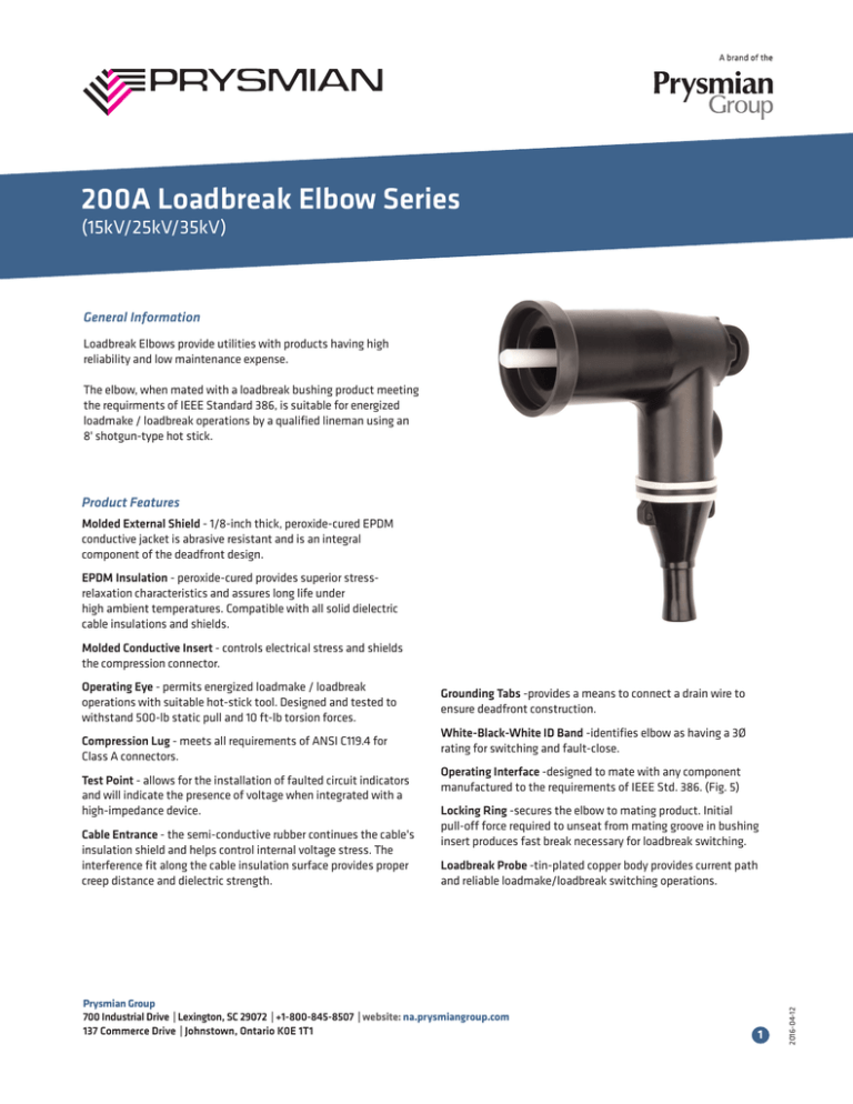
200A Loadbreak Elbow Series
(15kV/25kV/35kV)
General Information
Loadbreak Elbows provide utilities with products having high
reliability and low maintenance expense.
The elbow, when mated with a loadbreak bushing product meeting
the requirments of IEEE Standard 386, is suitable for energized
loadmake / loadbreak operations by a qualified lineman using an
8' shotgun-type hot stick.
Product Features
Molded External Shield - 1/8-inch thick, peroxide-cured EPDM
conductive jacket is abrasive resistant and is an integral
component of the deadfront design.
EPDM Insulation - peroxide-cured provides superior stressrelaxation characteristics and assures long life under
high ambient temperatures. Compatible with all solid dielectric
cable insulations and shields.
Molded Conductive Insert - controls electrical stress and shields
the compression connector.
Compression Lug - meets all requirements of ANSI C119.4 for
Class A connectors.
Test Point - allows for the installation of faulted circuit indicators
and will indicate the presence of voltage when integrated with a
high-impedance device.
Cable Entrance - the semi-conductive rubber continues the cable's
insulation shield and helps control internal voltage stress. The
interference fit along the cable insulation surface provides proper
creep distance and dielectric strength.
Grounding Tabs -provides a means to connect a drain wire to
ensure deadfront construction.
White-Black-White ID Band -identifies elbow as having a 3Ø
rating for switching and fault-close.
Operating Interface -designed to mate with any component
manufactured to the requirements of IEEE Std. 386. (Fig. 5)
Locking Ring -secures the elbow to mating product. Initial
pull-off force required to unseat from mating groove in bushing
insert produces fast break necessary for loadbreak switching.
Loadbreak Probe -tin-plated copper body provides current path
and reliable loadmake/loadbreak switching operations.
Prysmian Group
700 Industrial Drive | Lexington, SC 29072 | +1-800-845-8507 | website: na.prysmiangroup.com
137 Commerce Drive | Johnstown, Ontario K0E 1T1
1
2016-04-12
Operating Eye - permits energized loadmake / loadbreak
operations with suitable hot-stick tool. Designed and tested to
withstand 500-lb static pull and 10 ft-lb torsion forces.
Underground Connectors
General Information
Underground connectors provide utilities with products having high
reliability and low maintenance expense.
Separable connector bushing inserts and elbows are designed for
use with single-conductor, concentric neutral power cables having
extruded insulation shielding. With shield adapter products, the
elbow can be used with cables having a metallic tape shield, wire
shield, or lead sheath with tape or extruded insulation shielding.
All insulating and conducting rubber components are made of a
special formulation of an EPDM elastomer using a peroxide curing
process. The material and curing process provides superior
elastomer stress relaxation characteristics under high ambient
temperatures and contributes to reliable, long-time operation in
either above-ground or subsurface installations.
Elbow connector/bushing insert combinations are suitable for
energized loadmake/loadbreak operations by a qualified lineman
using an 8’ shotgun-type hot stick.
All elbow/bushing insert combinations are designed for use with
subsurface (submersible to 6-feet of water) or pad-mounted
installations.
8.3/4.4 - 25/28 kV Class Underground Connectors
General Information
- 10,000-amp fault-closing capability
- Piston-operated fault-close action
- Standard elbow and bushing insert loadbreak principle
- 1/8" thick molded shields
- Peroxide-cured EPDM compounds
- Full compliance with IEEE Standard 386 (Fig. 5)
Where to Use
15 kV loadbreak products are designed for operation on, and
connection to, 15 kV Class (95 kV BIL systems) where the voltage
ratings listed on this page are not exceeded.
25/28 kV loadbreak products are designed for operation on and
connection to 25/28 kV class, 125 kV BIL systems where the voltage ratings listed on this page are not exceeded.
General Information
Where to Use
- 10,000 ampere fault-closing capability
- Standard elbow and bushing loadbreak principle
- Molded shields
- Peroxide-cured EPDM compounds
- Full compliance with IEEE Standard 386
- 35kV Large Interface
- Purple cuffs for quick 35kV identification
35 kV loadbreak elbows are designed for operation on, and
connection to, 35 kV Class (150 kV BIL systems) where the
voltage ratings listed on this page are not exceeded.
Prysmian Group
700 Industrial Drive | Lexington, SC 29072 | +1-800-845-8507 | website: na.prysmiangroup.com
137 Commerce Drive | Johnstown, Ontario K0E 1T1
2
2016-04-12
21.1/36.6 kV Underground Elbow Connectors
RATINGS
15 kV
25/28 kV
35 kV
Max. continuous voltage:
8.3 kV phase-to-ground
14.4 kV phase-to-phase
16.2 kV phase-to-ground
28 kV phase-to-phase
21.1 kV phase-to-ground
36.6 kV phase-to-phase
Continuous current:
200-amp rms
200 amp rms
200 amp rms
SHORT-TIME CURRENT RATINGS
0.17-second duration
10,000-amp rms symmetrical
10,000 amp rms symmetrical
10,000 amp rms symmetrical
3.00-second duration
3,500-amp/rms symmetrical
3,500 amps rms symmetrical
3,500 amps rms symmetrical
INSULATION WITHSTAND VOLTAGES
Basic Impulse Level
95 kV crest
125 kV crest
150 kV crest
60 Hertz (1-minute)
34 kV rms
45 kV rms
50 kV rms
DC (15-minutes)
53 kV
84 kV
103 kV
Corona extinction voltage
(3-picocoulombs)
11 kV rms
21.5 kV rms
26 kV
(1.2 x 50 µsec wave)
ALL VOLTAGE CLASSES
10 loadmake/loadbreak
operations at 200 amps with
90% parallel and 10% series
resistance - reactance load at
0.8 power factor.
SWITCHING
1-phase and 3-phase circuits
8.3 kV phase-to-ground, 14.4
kV maximum across the
open contacts.
ALL VOLTAGE CLASSES
10,000 amps rms
symmetrical, 10 cycles
(0.17 seconds).
1-phase and 3-phase circuits
21.1 kV phase-to-ground, 36.6
kV maximum across the
open contacts.
FAULT CLOSURE
One fault-close operation
at 8.3 kV phase-to-ground,
or 14.4 kVphase-to-phase;
10,000 amps rms
symmetrical, 10 cycles,
(0.17 seconds).
ALL VOLTAGE CLASSES
100% factory test for
partial discharge
1-phase and 3-phase circuits
15.2 kV phase-to-ground, 26.3
kV maximum across the
open contacts.
One fault-close operation
at 15.2 kV phase-to-ground,
or 26.3 kV phase-to-phase;
10,000 amps rms
symmetrical, 10 cycles,
(0.17 seconds).
One fault-close operation
at 21.1 kV phase-to-ground,
or 36.6 kVphase-to-phase;
10,000 amps rms
symmetrical, 10 cycles,
(0.17 seconds).
PRODUCTION TESTS
100% factory test for partial
discharge and either AC
Hi-Pot (34kV for 60 seconds)
or impulse (BIL)
(95kV 1.2 x 50μ sec.).
100% factory test for partial
discharge and either AC
Hi-Pot (45kV for 60 seconds)
or impulse (BIL) 125kV, 1.2 x
50 microsecond wave.
100% factory test for partial
discharge and either AC
Hi-Pot (50kV for 60 seconds).
Prysmian Group
700 Industrial Drive | Lexington, SC 29072 | +1-800-845-8507 | website: na.prysmiangroup.com
137 Commerce Drive| Johnstown, Ontario K0E 1T1
3
2016-04-12
© PRYSMIAN - A Brand of The Prysmian Group 2016. All Rights Reserved. The information contained within this document must not be copied, reprinted or reproduced in any form,
either wholly or in part, without the written consent of Prysmian Group. The information is believed correct at the time of issue. Prysmian Group reserves the right to amend
any specifications without notice. These specifications are not contractually valid unless authorized by Prysmian Group. Issued January 2016.
200A Loadbreak Elbows with Test Point
Body
Part No.
Cable Insulation
Diameter Range (in.)
5kV 100%
5kV 133% / 8kV 100%
8kV 133%
15kV 100%
15kV 133%
15LB_3
0.498-0.730
#2 AWG - 4/0 AWG
#4 AWG - 3/0 AWG
#4 AWG - 2/0 AWG
#4 AWG to 1/0 AWG
-
15LB_4
0.635-0.905
2/0 AWG - 250 kcm
2/0 AWG - 250 kcm
1/0 AWG - 250 kcm
#2 AWG - 2/0 AWG
#2 AWG - 2/0 AWG
15LB_5
0.760-1.135
-
-
-
3/0 AWG - 250 kcm
3/0 AWG - 250 kcm
Body
Part No.
Cable Insulation
Diameter Range (in.)
25kV 100%
25kV 133%/28kV
100%
28kV 133%
2528LB_3
0.610-0.880
#4 AWG - #1 AWG
#4 AWG
-
2528LB_4
0.800-1.140
#1 AWG - 2/0 AWG
#1 AWG - 2/0 AWG
-
2528LB_5
0.920-1.310
3/0 AWG - 250 kcm
3/0 AWG - 250 kcm
-
2528LB_5A
0.920-1.310
-
-
1/0 AWG - 250 kcm
Body
Part No.
Cable Insulation
Diameter Range (in.)
35kV 100%
35kV 133%
35LB_5
1.020-1.310
1/0 AWG - 250 kcm
1/0 AWG - 4/0 AWG
Note: Replace " _" with "CN" for Conentric Neutral Cable
Example: For a 2/0 AWG Stranded 15kV 100% Cable with CN use body 15LBCN4-200LB6
Note : Replace "_" with "CTS" for Copper Tape Shield or LC Shield Cables
Example: For a 250 AWG Compact 15kV 133% Cable with LC or Copper Tape Shield use body 15LBCTS4-200LB8
Remember to add the required lug to the body part number per the Connector Table.
200A Connector Code
Part No.
Stranded / Compressed
Compact / Solid
200LB1
#6 AWG
#4 AWG
200LB2
#4 AWG, #3 AWG
#3 AWG, #2 AWG
200LB3
#2 AWG
#1 AWG
200LB4
#1 AWG
1/0 AWG
200LB5
1/0 AWG
2/0 AWG
200LB6
2/0 AWG
3/0 AWG
200LB7
3/0 AWG
4/0 AWG
200LB8
4/0 AWG
250 kcm
Prysmian Group
700 Industrial Drive | Lexington, SC 29072 | +1-800-845-8507 | website: na.prysmiangroup.com
137 Commerce Drive| Johnstown, Ontario K0E 1T1
4
2016-04-12
© PRYSMIAN - A Brand of The Prysmian Group 2016. All Rights Reserved. The information contained within this document must not be copied, reprinted or reproduced in any form,
either wholly or in part, without the written consent of Prysmian Group. The information is believed correct at the time of issue. Prysmian Group reserves the right to amend
any specifications without notice. These specifications are not contractually valid unless authorized by Prysmian Group. Issued January 2016.


