(E), pdf, 291KB, 1403 downloads
advertisement

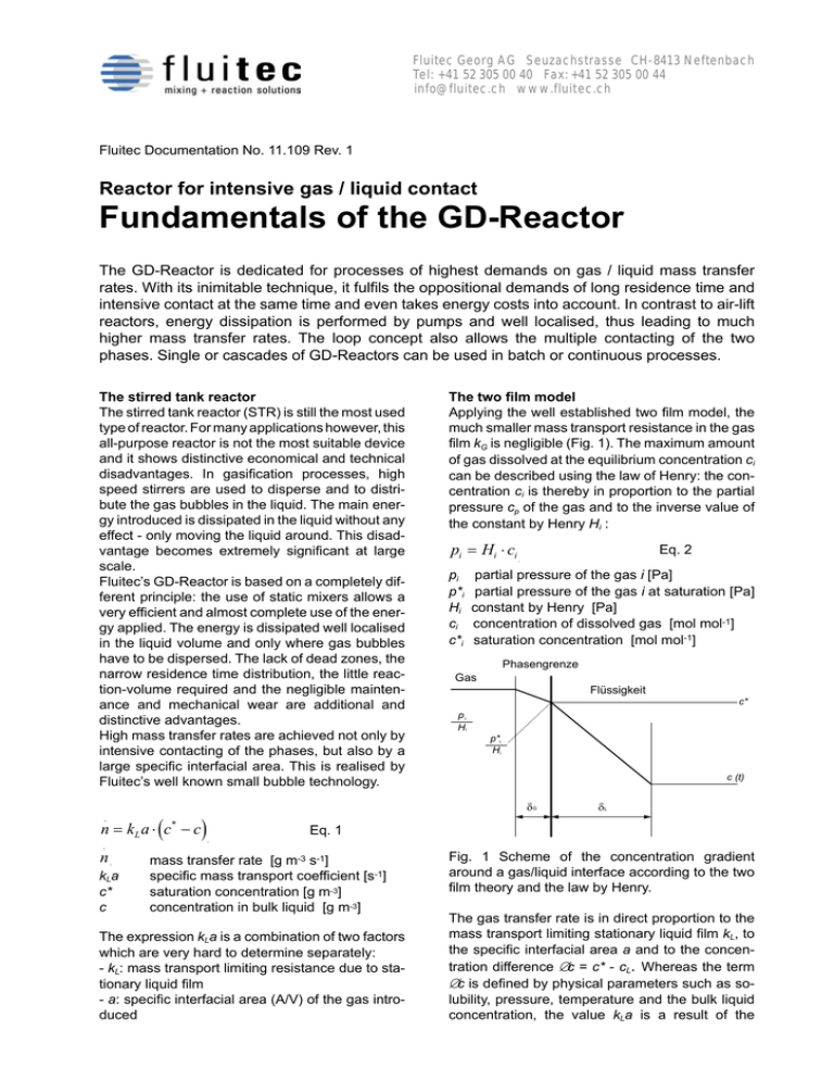
Fluitec Georg AG Seuzachstrasse CH-8413 Neftenbach Tel: +41 52 305 00 40 Fax: +41 52 305 00 44 info@ fluitec.ch www.fluitec.ch Fluitec Documentation No. 11.109 Rev. 1 Reactor for intensive gas / liquid contact Fundamentals of the GD-Reactor The GD-Reactor is dedicated for processes of highest demands on gas / liquid mass transfer rates. With its inimitable technique, it fulfils the oppositional demands of long residence time and intensive contact at the same time and even takes energy costs into account. In contrast to air-lift reactors, energy dissipation is performed by pumps and well localised, thus leading to much higher mass transfer rates. The loop concept also allows the multiple contacting of the two phases. Single or cascades of GD-Reactors can be used in batch or continuous processes. The stirred tank reactor The stirred tank reactor (STR) is still the most used type of reactor. For many applications however, this all-purpose reactor is not the most suitable device and it shows distinctive economical and technical disadvantages. In gasification processes, high speed stirrers are used to disperse and to distribute the gas bubbles in the liquid. The main energy introduced is dissipated in the liquid without any effect - only moving the liquid around. This disadvantage becomes extremely significant at large scale. Fluitec’s GD-Reactor is based on a completely different principle: the use of static mixers allows a very efficient and almost complete use of the energy applied. The energy is dissipated well localised in the liquid volume and only where gas bubbles have to be dispersed. The lack of dead zones, the narrow residence time distribution, the little reaction-volume required and the negligible maintenance and mechanical wear are additional and distinctive advantages. High mass transfer rates are achieved not only by intensive contacting of the phases, but also by a large specific interfacial area. This is realised by Fluitec’s well known small bubble technology. n = k L a ⋅ (c − c ) . * The two film model Applying the well established two film model, the much smaller mass transport resistance in the gas film kG is negligible (Fig. 1). The maximum amount of gas dissolved at the equilibrium concentration ci can be described using the law of Henry: the concentration ci is thereby in proportion to the partial pressure cp of the gas and to the inverse value of the constant by Henry Hi : pi = Hi ⋅ ci pi p*i Hi ci c*i Eq. 2 partial pressure of the gas i [Pa] partial pressure of the gas i at saturation [Pa] constant by Henry [Pa] concentration of dissolved gas [mol mol-1] saturation concentration [mol mol-1] Phasengrenze Gas Flüssigkeit c* pi Hi p*i Hi c (t) δG δL Eq. 1 . n kLa c* c mass transfer rate [g m-3 s-1] specific mass transport coefficient [s-1] saturation concentration [g m-3] concentration in bulk liquid [g m-3] The expression kLa is a combination of two factors which are very hard to determine separately: - kL: mass transport limiting resistance due to stationary liquid film - a: specific interfacial area (A/V) of the gas introduced Fig. 1 Scheme of the concentration gradient around a gas/liquid interface according to the two film theory and the law by Henry. The gas transfer rate is in direct proportion to the mass transport limiting stationary liquid film kL, to the specific interfacial area a and to the concentration difference ∆c = c* - cL. Whereas the term ∆c is defined by physical parameters such as solubility, pressure, temperature and the bulk liquid concentration, the value kLa is a result of the hydrodynamics caused by the reactor used. In numerous processes, neither in-line gasification nor air-lift devices are suitable for high performance gasification. A combination of both would be of advantage, e.g. in the following cases: Di - high gas volume compared to the liquid volume - high energy dissipation needed (e.g. coalescence supporting or highly viscous media) - long contact time required (e.g. due to slow chemical reaction) - high heat transfer required due to strong exothermic reactions (e.g. combinations with the Fluitec CSE-XR Heat Exchanger Reactor) 1) a special pump guarantees the high liquid speed, which is required to shear-off the small gas bubbles at the porous FSBR-dosage site even at higher viscosities (high value for a). 2) the following mixing- and contacting device is extremely energy saving due to the constant and well localised energy dissipation. The stationary liquid film, which surrounds the bubbles, is significantly reduced by the turbulences and the interfacial surfaces are continuously renewed (high value for kL) 3) the reactor vessel allows a long contact time of the two phases 4) if the gas has to be dissolved completely, e.g. due to economically or toxically reasons, the gas is continuously re-introduced in a second loop by an injector. The gas circulates continuously until the desired concentrations in the head-space are reached. Flüssigkeit Gas L Fig. 2 FSBR DN 8 in Swagelok-screw joint The GD-Reactor The GD-Reactor concept unifies all the advantages of air-lift and in-line gasification, while eliminating the disadvantages at the same time. This concept has been developed and investigated in collaboration with the Zurich University of Applied Sciences Winterthur (ZHW) and a large chemical company. Fluitec possesses the exclusive license to build this type of reactor. The GD-Reactor can be divided in 4 main sections (Fig. 3). 1 HTS 10 PI Gas-Austritt 1 HTS 10 CP101 AA101 Fig. 4 Micro bubbles in the GD Reactor (CSE-X) PI 1 HTS 10 CP001 FSBR 1a 1 HTS 10 SM101 Gas-Eintritt CSE-VT 4 WT 1 HTS 10 SM103 1 HTS 10 WT001 2 Reaktor-Tank 1 HTS 10 TA001 CSE-X 1 HTS 10 SM102 3 Verteilung M 1 Fig. 3 Flow chart of a GD-Reactor Version 101 The GD-Reactor can be operated continuously and put in a cascade. Large volumes of bad soluble, toxic, expensive or reactive gases can be dissolved in this way, if the gas and the liquid media flow in counter current. After specific laboratory tests, the equilibrium concentrations can be calculated by computer models. For very strong exo- or endothermic reaction, the combination with the Fluitec CSE-XR Heat Exchanger Reactor is recommended. In contrast to plate heat exchangers, there are no dead zones and there is an intensive and continuous energy dissipation. In this way, the reaction is always under absolute control and the security precautions can be drastically reduced.


