T 1.2/1/EN/2
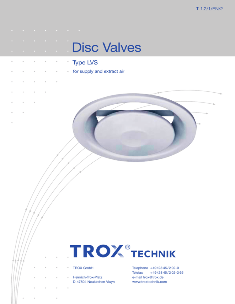
Disc Valves
Type LVS
for supply and extract air
TROX GmbH
Heinrich-Trox-Platz
D-47504 Neukirchen-Vluyn
Telephone +49 / 28 45 / 2 02-0
Telefax
+49 / 28 45 / 2 02-2 65
e-mail trox@trox.de
www.troxtechnik.com
Contents · Description · Construction · Materials
Description
Construction · Materials
Dimensions · Installation
Quick Selection Table
Nomenclature · Aerodynamic Data
Acoustic Data
Order Details
2
2
3
3
4
5
6
LVS
Z-LVS
Description
Construction
Type LVS disc valves are suitable for all types of ventilation
systems. They have been redesigned and thus satisfy the
highest standards for comfort criteria.
Depending on the application, different constructions for supply
(type Z-LVS) and extract air (type LVS) are available.
This disc valves consist of the valve ring and central disc.
By rotating the central disc, the air volume flow rate can be
changed. This results in changes to acoustic and pressure drop
figures.
To guarantee a perfect seat, the valve ring is fitted with a
peripheral sealing strip.
The air volume flow rate is adjusted by rotating the central disc
which alters the size of the gap. The central disc is held in
position with a locknut.
Material
Face sections made of sheet steel with electrostatic powder
coating (similar to RAL 9010, coating thickness 60 µm),
threaded spindle and nut made of galvanised steel,
installation subframe made of galvanised sheet steel.
2
Dimensions · Installation Details · Quick Selection Table
Dimensions
C
D
D1
E *
Weight
in kg
100
40
99
132
125
104
0.200
125
46
124
162
150
129
0.290
Z-LVS
Size
.
V
in m3/h
.
V
in l/s
∆pt
in Pa
LWA
in dB(A)
L
in m
100
115
32
130
40
–
125
180
50
135
40
–
160
260
72
125
40
–
160
54
159
205
185
164
0.440
200
61
199
245
225
204
0.590
200
350
97
110
40
–
100
40
99
132
125
104
0.230
100
100
28
37
40
1.7
125
46
124
162
150
129
0.320
125
155
43
77
40
2.5
160
54
159
205
185
164
0.500
160
235
65
90
40
4.0
200
61
199
245
225
204
0.670
200
290
81
90
40
4.6
Z-LVS
LVS
Type
LVS
B
s = 0 mm
Size
s = 12 mm
Type
Quick selection table (for nomenclature see page 4)
* Dimension E must be adjusted according to the line used!
LVS
Installation Details
The LVS and Z-LVS units are supplied with subframe.
A bayonet fixing is used to locate the unit in the subframe.
D
C
E *
50
Installation subframe for LVS and Z-LVS
(9)
8
C
( ) – NW 160/200
D1
B
Z-LVS
50
50
D
C
E *
Mounting the installation subframe
with screws through the holes provided
in the flange.
(9)
8
B
( ) – NW 160/200
3
Nomenclature · Aerodynamic Data
LVS
Nomenclature
‡
L
L
in mm: Gap size
in m/s: Time average air velocity
at the wall
L
pt
in Pa: Total pressure drop
in dB(A): A-weighted sound power level
LWA
LW NC
: NC rating of sound power level
LW NR
: LW NR = LW NC + 3
L pA, L pNC
: A weighting or NC rating respectively of room
sound pressure level L pA L WA – 8 dB
L pNC L W NC – 8 dB
Definition of the throw distance
-v = 0.2 m/s
L
Throw distance
3
5
5
4
4
3
3
2
2
1.5
1
0.8
0.7
4
5
5
4
4
3
3
2
2
1
0.8
0.7
Size 200
0.7
0.5
1.5
Throw distance
0.8
0.5
Size 125
Size 160
1
0.6
Throw distance
Throw distance
1.5
0.6
2
Throw distance L in mm
Size 100
Throw distance L in mm
Throw distance L in mm
1
Throw distance L in mm
s
v-
Z-LVS
in l/s or m3/h: Volume flow rate per disc valve
in m: Throw distance related to v- = 0.2 m/s
1.5
1
0.8
0.7
0.6
0.6
0.5
0.5
4
Acoustic Data – Extract Air · Supply Air
Extract air – Sound power level and Pressure drop – Type LVS
7
Size 160
Example
Data given:
Z-LVS / Size 125
Volume flow
per disc valve
Gap size
Pressure drop p t in Pa
Size 100
Pressure drop p t in Pa
5
Diagram 10:
Sound power level and Pressure drop
L WA = 37 dB(A) (L WNC = 32 NC)
p t = 65 Pa
Diagram 2:
L
= 2.4 m
8
Size 125
Size 200
Throw distance
At a distance of L = 2.4 m, the time
average air velocity ƒ L = 0.2 m/s.
Pressure drop p t in Pa
Pressure drop p t in Pa
6
‡ = 40 l/s
s = 12 mm
Supply air – Sound power level and Pressure drop – Type Z-LVS
Size 100
10
Size 125
Size 160
12
Size 200
Pressure drop p t in Pa
Pressure drop p t in Pa
Pressure drop p t in Pa
11
Pressure drop p t in Pa
9
5
Order Details
Order Code
LVS
Supply air
Extract air
Z-LVS
LVS
IEE
EE
EE
OEE
EE
EEE
P
/
125
/
100
125
160
200
Size
G1
TEE
EZ 0
EEE G1
U
Without installation subframe
Installation subframe1)
(standard)
Design changes reserved · All rights reserved © TROX GmbH (8/2008)
1) If not stated, installation subframe (G1)
will be supplied
Specification Text
Circular disc valves, suitable for supply and extract air,
comprising valve ring with peripheral seal, central disc with
threaded spindle and locknut and installation subframe with
volume flow rate adjustment by rotating the central disc.
Material
Face sections sheet steel with electrostatic powder coating
(colour similar to RAL 9010, thickness 60 µm), galvanised
steel threaded spindle and lock nut, installation subframe
galvanised sheet steel.
6
Order Example
Make:
Type:
TROX
LVS / 125 / G1


