EZ-WRAP® Side Tie - Preformed Line Products
advertisement

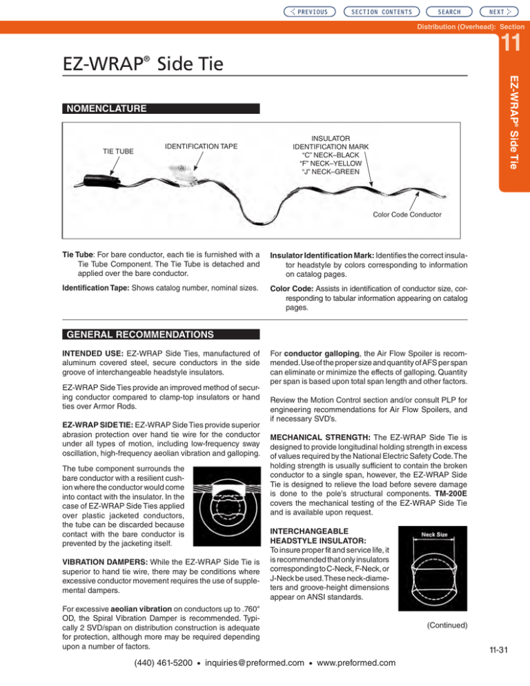
PREVIOUS SECTION CONTENTS SEARCH NEXT Distribution (Overhead): Section 11 EZ-WRAP Side Tie ® EZ-WRAP® Side Tie NOMENCLATURE TIE TUBE IDENTIFICATION TAPE INSULATOR IDENTIFICATION MARK “C” NECK–BLACK “F” NECK–YELLOW “J” NECK–GREEN Color Code Conductor Tie Tube: For bare conductor, each tie is furnished with a Tie Tube Component. The Tie Tube is detached and applied over the bare conductor. Insulator Identification Mark: Identifies the correct insulator headstyle by colors corresponding to information on catalog pages. Identification Tape: Shows catalog number, nominal sizes. Color Code: Assists in identification of conductor size, corresponding to tabular information appearing on catalog pages. GENERAL RECOMMENDATIONS INTENDED USE: EZ-WRAP Side Ties, manufactured of aluminum covered steel, secure conductors in the side groove of interchangeable headstyle insulators. EZ-WRAP Side Ties provide an improved method of securing conductor compared to clamp-top insulators or hand ties over Armor Rods. EZ-WRAP SIDE TIE: EZ-WRAP Side Ties provide superior abrasion protection over hand tie wire for the conductor under all types of motion, including low-frequency sway oscillation, high-frequency aeolian vibration and galloping. The tube component surrounds the bare conductor with a resilient cushion where the conductor would come into contact with the insulator. In the case of EZ-WRAP Side Ties applied over plastic jacketed conductors, the tube can be discarded because contact with the bare conductor is prevented by the jacketing itself. VIBRATION DAMPERS: While the EZ-WRAP Side Tie is superior to hand tie wire, there may be conditions where excessive conductor movement requires the use of supplemental dampers. For conductor galloping, the Air Flow Spoiler is recommended. Use of the proper size and quantity of AFS per span can eliminate or minimize the effects of galloping. Quantity per span is based upon total span length and other factors. Review the Motion Control section and/or consult PLP for engineering recommendations for Air Flow Spoilers, and if necessary SVD’s. MECHANICAL STRENGTH: The EZ-WRAP Side Tie is designed to provide longitudinal holding strength in excess of values required by the National Electric Safety Code. The holding strength is usually sufficient to contain the broken conductor to a single span, however, the EZ-WRAP Side Tie is designed to relieve the load before severe damage is done to the pole's structural components. TM-200E covers the mechanical testing of the EZ-WRAP Side Tie and is available upon request. INTERCHANGEABLE HEADSTYLE INSULATOR: To insure proper fit and service life, it is recommended that only insulators corresponding to C-Neck, F-Neck, or J-Neck be used.These neck-diameters and groove-height dimensions appear on ANSI standards. For excessive aeolian vibration on conductors up to .760" OD, the Spiral Vibration Damper is recommended. Typically 2 SVD/span on distribution construction is adequate for protection, although more may be required depending upon a number of factors. (440) 461-5200 • inquiries@preformed.com • www.preformed.com (Continued) 11-31 PREVIOUS SECTION CONTENTS SEARCH EZ-WRAP® Side Tie GENERAL RECOMMENDATIONS CONTD. Consult PLP for engineering recommendations on noninterchangeable headstyle insulators. A sample of the insulator in question is desirable. CONDUCTOR SIZE: The EZ-WRAP Side Tie exactly matches the DISTRIBUTION Ties’ ranges, which means identical color codes on armless construction. Conductor sizes up to 1.240" O.D. can be accommodated depending on the insulator's side groove radius. The EZ-WRAP Side Tie is designed to permit controlled movement of unbroken conductor, reducing cantilever loading at the base of the insulator or bracket, then restore itself. We refer to this unique feature as “resilience”. RADIO INTERFERENCE: The RIV/TVI characteristics of EZ-WRAP Side Ties are equivalent to those of a wellmade hand tie when originally installed. During service life the precontoured EZ-WRAP Side Tie assures continued fit, which would have better RIV/TVI performance than a loosened tie wire. rods will remain permissible, however, there are now stirrups available that provide a superior method of making hot-line taps. LINE ANGLES GENERAL GUIDELINES: On horizontally-mounted insulators, EZWRAP Side Ties can normally accommodate line angles up to 10°. On vertically-mounted insulators, line angles up to 40° can normally be achieved. When insulators are mounted at various degrees of cant between the horizontal and the vertical, line angles between 0° and 40° may be accommodated depending upon the actual cant of the insulator. In all cases, the conductor should rest in the preferred insulator groove, independently of the tie, so the tie is not required to force the conductor to remain in that groove. The largest practical angle a tie can accommodate depends upon limiting factors such as conductor size, tension, span lengths, sag angles, insulator style and orientation, etc. Consult PLP® for further guidance on line angle issues not covered in the above test report. TAPPING: Compared to the use of protective rods, placing hot-line clamps directly over the applied legs of EZ-WRAP Side Ties cannot be recommended. Tapping over protective SAFETY CONSIDERATIONS 1. This product is intended for a single (one-time) use and for the specified application. CAUTION: DO NOT REUSE OR MODIFY THIS PRODUCT UNDER ANY CIRCUMSTANCES. 2. This product is intended for use by trained craftspeople only. This product SHOULD NOT BE USED by anyone who is not familiar with and trained in the use of it. 4. For PROPER PERFORMANCE AND PERSONAL SAFETY be sure to select the proper size EZ-WRAP Side Tie before application. 5. EZ-WRAP Side Ties are precision devices. To insure proper performance, they should be stored in cartons under cover and handled carefully. 3. When working in the area of energized lines with this product, EXTRA CARE should be taken to prevent accidental electrical contact. 11-32 (440) 461-5200 • inquiries@preformed.com • www.preformed.com NEXT SECTION CONTENTS PREVIOUS SEARCH NEXT Distribution (Overhead): Section 11 EZ-WRAP Side Tie ® EZ-WRAP® Side Tie For use on: ACAR, ACSR, All-Aluminum, AWAC® Compacted ACSR, Aluminum Alloy C-Neck Interchangeable Headstyle Insulators ANSI 55-2 PIN ANSI 55-3 PIN Catalog Number 2-1/4" Neck Diameter Diameter Range (Inches) Units Wt./Lbs. Per Carton Approx. Applied Length (Inches) Insulator Identification Mark Color Code Min. Max. Nominal Conductor Size .190 .215 #6, 6/1 #4, 7W Comp. 100 16 21 Black Blue 100 17 22 Black Brown 9/16" R. GROOVE (See Note 2) EZSTC-270 EZSTC-271 .216 .244 #4, 7W, All Alum. #4, 6/1, 7/1 Comp. EZSTC-272 .245 .277 #4, 6/1 7/1 #4, 7W, Alum. Alloy 100 18 23 Black Orange 100 18 24 Black Purple EZSTC-273 .278 .315 #3, 7W, Alum. Alloy #2, 7W, All Alum. EZSTC-274 .316 .357 #2, 6/1 - 7/1 #2, 7W, Alum. Alloy #1, 6/1 100 19 25 Black Red EZSTC-275 .358 .405 1/0, 7W All Alum. 1/0, 6/1 1/0, 7W, Alum. Alloy 100 21 23 Black Yellow EZSTC-276 .406 .459 2/0, 7W All Alum. 2/0, 6/1 2/0, 7W Alum. Alloy 100 22 25 Black Blue 100 24 27 Black Orange EZSTC-277 .460 .520 3/0, 7W All Alum. 3/0, 6/1 3/0, 7W, Alum. Alloy EZSTC-278 .521 .588 4/0, 7W All Alum. 4/0, 6/1 4/0 7W, Alum Alloy 100 30 28 Black Red EZSTC-279 .589 .665 266.8, 37W All Alum. 266.8, 18/1 336.4, 19W All Alum. 100 34 31 Black Purple EZSTC-280 .666 .755 336.4, 37W All Alum. 336.4, 18/1 397.5, 19W All Alum. 400, 19W, 37W All Alum. 100 35 33 Black Brown EZSTC-281 .756 .858 477, 19W, 37W, All Alum. 477, 18/1, 24/7, 26/7 50 29 35 Black Red 35 36 Black Blue 38 38 Black Green 38 39 Black Yellow 5/8" R. GROOVE (See Note 2) EZSTC-282 .859 .968 556.5, 26/7, 636, 18/1 700, 37W, 61W, All Alum. 1.096 795, 37W, 61W, All Alum. 715.5, 24/7 795, 54/7 1.240 954, 36/1, 54/7 1033.5, 37W, 61W, All Alum. 50 11/16" R. GROOVE (See Note 2) EZSTC-283 .969 50 3/4" R. GROOVE (See Note 2) EZSTC-284 1.097 50 Right-hand lay standard EXPLANATORY NOTES: (1) (2) (3) Nominal Conductor size indicates one of various conductors within each range. For the succeeding ranges, the insulator’s side groove radius should be at least as large as shown above. AWAC is a registered trademark of the Copperweld Co. 11-33 (440) 461-5200 • inquiries@preformed.com • www.preformed.com SECTION CONTENTS PREVIOUS SEARCH EZ-WRAP® Side Tie For use on: ACAR, ACSR, All-Aluminum, AWAC® Compacted ASCR, Aluminum Alloy F-Neck Interchangeable Headstyle Insulators ANSI 53-4 Spool ANSI 53-5 Spool ANSI 55-4 Pin ANSI 55-5 Pin ANSI 57-1 Post ANSI 57-2 Post ANSI 57-3 Post Catalog Number 2-7/8" Neck Diameter Diameter Range (Inches) Units Wt./Lbs. Per Carton Applied Length (Inches) Insulator Identification Mark Color Code Min. Max. Nominal Conductor Size EZSTF-170 .190 .215 #6, 6/1 – #4, 7W Comp. 100 16 21 Yellow Blue EZSTF-171 .216 .244 #4, 7W All Alum. – #4, 6/1, 7/1 Comp. 100 17 22 Yellow Brown EZSTF-172 .245 .277 #4, 6/1, 7/1 – #4, 7W Alum. Alloy 100 18 23 Yellow Orange EZSTF-173 .278 .315 #3, 7W Alum. Alloy – #2, 7W All Alum. 100 18 24 Yellow Purple EZSTF-174 .316 .357 #2, 6/1, 7/1 – #2, 7W Alum. Alloy #1, 6/1 100 19 25 Yellow Red 100 21 23 Yellow Yellow 9/16" R. GROOVE (See Note 2) EZSTF-175 .358 .405 1/0, 7W All Alum. 1/0, 6/1 1/0, 7W Alum. Alloy EZSTF-176 .406 .459 2/0, 7W All Alum. 2/0, 6/1 2/0, 7W Alum. Alloy 100 22 25 Yellow Blue EZSTF-177 .460 .520 3/0, 7W All Alum. 3/0, 6/1 3/0, 7W Alum. Alloy 100 24 27 Yellow Orange EZSTF-178 .521 .588 4/0, 7W All Alum. 4/0, 6/1 4/0, 7W Alum. Alloy 100 30 28 Yellow Red EZSTF-179 .589 .665 266.8, 37W All Alum. 266.8, 18/1 336.4, 19W All Alum. 100 34 31 Yellow Purple EZSTF-180 .666 .755 336.4, 37W All Alum. 336.4, 18/1 397.5, 19W All Alum. 400, 19W, 37W All Alum. 100 34 34 Yellow Brown EZSTF-181 .756 .858 477, 19W, 37W, All Alum. 477, 18/1, 24/7, 26/7 50 54 36 Yellow Red .968 556.5, 26/7, 636, 18/1 700, 37W, 61W, All Alum. 36 37 Yellow Blue 39 39 Yellow Green 40 40 Yellow Yellow 5/8" R. GROOVE (See Note 2) EZSTF-182 .859 50 11/16" R. GROOVE (See Note 2) EZSTF-183 .969 1.096 795, 37W, 61W, All Alum. 715.5, 24/7 795, 54/7 EZSTF-184 1.097 1.240 954, 36/1, 54/7 1033.5, 37W, 61W, All Alum. 50 3/4" R. GROOVE (See Note 2) 50 Right-hand lay standard EXPLANATORY NOTES: (1) (2) (3) Nominal Conductor size indicates one of various conductors within each range. For the succeeding ranges, the insulator’s side groove radius should be at least as large as shown above. AWAC is a registered trademark of the Copperweld Co. 11-34 (440) 461-5200 • inquiries@preformed.com • www.preformed.com NEXT SECTION CONTENTS PREVIOUS SEARCH NEXT Distribution (Overhead): Section 11 EZ-WRAP Side Tie ® EZ-WRAP® Side Tie For use on: ACSR, ACAR, All-Aluminum, AWAC®, Compacted ACSR, Aluminum Alloy J-Neck Interchangeable Headstyle Insulators ANSI 55-6 Single Skirt Pin ANSI 55-7 Single Skirt Pin ANSI 56-1 Double Skirt Pin Catalog Number 3-1/2" Neck Diameter Diameter Range (Inches) Min. Max. Units Nominal Conductor Size Wt./Lbs. Per Carton Applied Length (Inches) Insulator Identification Mark Color Code 9/16" R. GROOVE (See Note 2) EZSTJ-570 .190 .215 #6, 6/1 100 18 24 Green Blue EZSTJ-571 .216 .244 #4, 7W, All Alum. 100 19 25 Green Brown EZSTJ-572 .245 .277 #4, 6/1 - 7/1 #3, 7W, All Alum. 100 19 26 Green Orange 100 20 27 Green Purple EZSTJ-573 .278 .315 #3, 7W, Alum. Alloy #2, 7W, All Alum. EZSTJ-574 .316 .357 #2, 6/1 - 7/1 #2, 7W, Alum. Alloy #1, 6/1 100 21 28 Green Red EZSTJ-575 .358 .405 1/0, 7W-19W All Alum. 1/0, 6/1 1/0, 7W, Alum. Alloy 100 23 26 Green Yellow EZSTJ-576 .406 .459 2/0, 7W-19W, All Alum. 2/0, 6/1 100 25 28 Green Blue EZSTJ-577 .460 .520 3/0, 7W-19W, All Alum. 3/0, 6/1 3/0, 7W, Alum. Alloy 100 26 30 Green Orange EZSTJ-578 .521 .588 4/0, 6/1 4/0, 7W, All Alum. 4/0, 7W, Alum Alloy 250, 19W-37W All Alum. 100 35 31 Green Red EZSTJ-579 .589 .665 266.8, 19W-37W All Alum. 300, 19W37W, All Alum. 266.8, 26/7 100 38 34 Green Purple 5/8" R. GROOVE (See Note 2) EZSTJ-580 .666 .755 336.4, 37W, All Alum. 397.5, 19W-37W, All Alum. 50 40 36 Green Brown EZSTJ-581 .756 .858 397.5, 24/7, 26/7 477, 19W, 37W, All Alum. 477, 18/1, 24/7, 26/7 50 31 38 Green Red EZSTJ-582 .859 .968 556.5, 61W All Alum. 556.5, 26/7 636, 18/1 50 38 39 Green Blue EZSTJ-583 .969 1.096 636, 24/7, 26/7, 30/19 715.5, 36/1, 24/7, 26/7 50 40 41 Green Green EZSTJ-584 1.097 1.240 954, 54/7 1033.5, 45/7 1113, 61W All Alum. 954, 37W Alum. Alloy 50 43 42 Green Yellow Right-hand lay standard EXPLANATORY NOTES: (1) (2) (3) Nominal Conductor size indicates one of various conductors within each range. For the succeeding ranges, the insulator’s side groove radius should be at least as large as shown above. AWAC is a registered trademark of the Copperweld Co. 11-35 (440) 461-5200 • inquiries@preformed.com • www.preformed.com SECTION CONTENTS PREVIOUS SEARCH Insulator Fit Interchangeable Insulators for use with PLP® Ties Dimensional Factors that affect Tie Application and Performance Shoulder Dia. Top Groove to Side Groove Distance 4. 2. Neck Diameter Top Groove Radius Saddle Length 3. 1. Groove Depth Side Groove Radius It is recommended that only insulators meeting the dimensional requirements of the most recent ANSI® C29.3, C29.5, C29.6, and C29.7 specifications be used with the appropriate PLP ties. ANSI C29 Insulator Specifications and their Affects on PLP Ties ANSI C29 specifies and defines dimensions for insulator heads that are crucial to the proper application and lifetime performance of PLP factory formed ties. These dimensions include: •Neck Diameter - nominal -C-neck – 2-1/4" -F-neck – 2-7/8" -J-neck – 3-1/2" -K-neck – 4" •Top groove radius (minimum) •Side groove radius (minimum) •Maximum shoulder diameter (maximum) •Top groove to side groove vertical spacing Some of the specified dimensions are simply maximum or minimum allowable values. The dimensions for the vertical distance from the bottom of the top groove to the middle of the side groove and the neck diameter have minimum and maximum values designated. These dimensions and insulator designations determine the proper tie to be used and the maximum conductor size for the groove application. Review the individual tie sections for groove/conductor diameter limitations. Each of these items has different results on a factory formed tie's performance. Combinations of several of these characteristics could result in initial tie damage and incorrect application. 1. The transition contour of the top groove into the side groove is important due to the tie’s shape. If an edge is created instead of a smooth rounded transition, the tie’s formed wire is forced to bend over a fulcrum point resulting in a high concentration of stress. This is detrimental for both the insulator and tie. C-neck Insulator F-neck Insulator Figure 1a Note the edge that exists between the top groove and the side groove above. Figure 1b shows a smooth transition. Insulator characteristics that are not part of the ANSI C29 Specifications 11-2 Some of the insulator characteristics that have an impact on the application and performance of PLP Ties are not included in the ANSI specification. These characteristics include: 1. The transition contour of the top groove into side groove 2. Length of the saddle or top groove 3. Extension of shoulders past the edge of the top groove. 4. Depth of the top groove Figure 1b (440) 461-5200 • inquiries@preformed.com • www.preformed.com NEXT PREVIOUS SECTION CONTENTS SEARCH NEXT Distribution (Overhead): Section 11 Insulator Fit Insulator Fit 2. A top groove length longer than the insulator’s neck diameter results in an edge. This edge creates a high stress contact point and results in an abnormal tie application. As an example, Figure 2 illustrates how a Distribution Tie reacts to this configuration (the tie tube was omitted to illustrate the gap beneath the conductor). Note the point contact at the insulator/tie interface. The circled area illustrates that the covered center section of the WRAPLOCK® Tie is wedged between the conductor and the inner surface of the insulator. This increases the installation difficulty of the tie. In many instances the transition of the grooves can have a great impact on the form, fit, and function of a factory formed tie and hand tie wire. The sharp edge of a long top groove saddle (see Figure #1) can be especially hazardous to the soft hand tie wire as well as a factory formed tie. Insulator Review and Trial Applications It is recommended the user conduct a thorough review of the insulator size, shape and geometry and conduct trial fits with the ties, prior to full scale field installations. Consult PLP for assistance, especially if there are any doubts concerning tie and insulator fit or performance. Figure 2 Non-ANSI C29 Insulators 3. The shoulder extensions result in difficulty in application of top ties. As the tie is rotated, the added protrusions from the shoulders past the end of the top groove provide catch points for the tie (see F-neck Insulator in Figure 1a). Some insulators that do not technically meet all the ANSI C29 Wet Process Porcelain Insulator standards may be suitable for use with PLP factory formed ties depending on their head and neck dimensions and geometry. An example is the PLP polymer C & F-neck tie top insulators. These insulators have head and neck designs for use with PLP factory formed ties or PLP Ring Ties. The head and neck dimensions of the PLP Polymer C & F-neck insulators have been designed to match critical ANSI C29 dimensional specifications and meet or exceed most of the mechanical and electrical performance requirements specified in that standard. Figure 3 4.The top groove of the insulator can cause installation difficulties of top ties when its diameter is at the minimum ANSI designation. This is especially troublesome when installing the WRAPLOCK® Tie. Figure 3 illustrates the application on a C-neck insulator on 1/0 ACSR 6/1 conductor. PLP Polymer 15kV and 35kV Insulators 11-3 (440) 461-5200 • inquiries@preformed.com • www.preformed.com


